This thread has been locked.

If you have a related question, please click the "Ask a related question" button in the top right corner. The newly created question will be automatically linked to this question.

DRV8872-Q1: max voltage of pin out2

Part Number: DRV8872-Q1
Other Parts Discussed in Thread: DRV8872EVM

Dear expert:
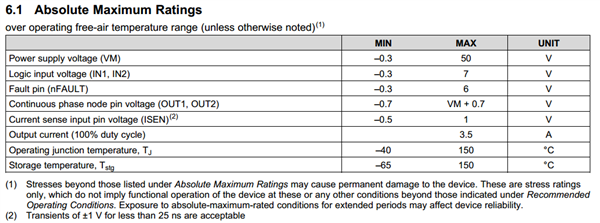
Question1: What's the max voltage of pin out2, 12.7V or 50.7V? Considering VM is 12V in my application. Continuous phase node pin voltage (out1,out2) is found to be VM+0.7V in table6.1.
Question1: Now I want to pass one EE test: pin out2 short to 32V for 60s when VM is not present. Will DRV8872Q1 be damaged?

  • Hi Lin,

    If VM = 0V or  12V, shorting OUT2 to 32V is a violation of absolute maximums, and may cause damage.

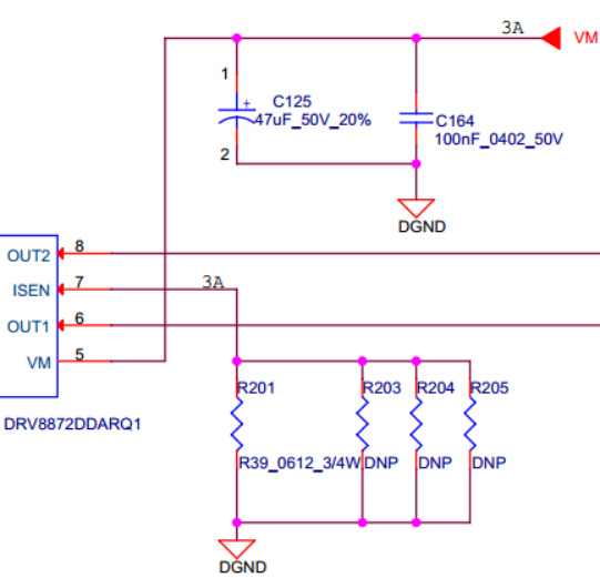
    The current will flow through the body diode of the high side FET to charge the 47uF capacitor. The capacitor inrush current cannot be controlled.

    If a short to 32V can occur, please consider adding a schottky rated for the inrush current from OUT1/OUT2 to VM.

  • HI RICK

    How to confirm inrush current please?

    VM is supplied by DCDC VOUT, should DCDC VOUT capacitor also be considered?

    Thanks!

  • HI RICK

    Will fault be triggered under following three cases?

    case1: out2 is connected to 32V, current flows through body diode to VM.

    case2: out2 is connected to 32V, current flows through HS-FET channel to VM.

    case3: out2 is connected to 32V, current flows through LS-FET channel to VM.

    FAULT.pdf

  • Hi Lin,

    The inrush current can be very high, depending on the 32V bulk capacitor.

    The equivalent circuit that is created is 32V capacitor through a diode to VM capacitor. 

    To answer your fault questions: 

    Will fault be triggered under following three cases?

    case1: out2 is connected to 32V, current flows through body diode to VM. -- No, current is not detected when following from source to drain

    case2: out2 is connected to 32V, current flows through HS-FET channel to VM. -- No, current is not detected when following from source to drain

    case3: out2 is connected to 32V, current flows through LS-FET channel to VM. -- Yes, but prior to this, current has flowed through the body diode of the high side FET.

  • Hi rick

    Q1:OCP fault will be triggered, once current flowwing through drain to source exceeds speficied, whatever HS or LS. Am I right? Can you detail the OCP detection method, or share me one document, please?

    Q2: For case3, why do you say "but prior to this, current has flowed through the body diode of the high side FET"?  I think the body diode is more resistive than DS channel?

  • Hi Lin,

    Q1:OCP fault will be triggered, once current flowwing through drain to source exceeds speficied, whatever HS or LS. Am I right? Can you detail the OCP detection method, or share me one document, please?


    You are correct. The drain to source currents is monitored using internal circuitry. If the current exceeds the OCP value (3.7 to 6.6A )for the OCP deglitch time (~2us), the FETs are disabled for ~3ms.


    Q2: For case3, why do you say "but prior to this, current has flowed through the body diode of the high side FET"?  I think the body diode is more resistive than DS channel?


    This depends on when the output is enabled.

    If the short to 32V occurs prior to the outputs enabled, the current flows through the body diode of the high side FET.

    If the short occurs when the output is high, the current flows through the high side FET.

    If the short occurs when the output is low, the current flows through the low side FET and causes and overcurrent fault.

  • Hi rick

    I appreciate so much for your kind help.

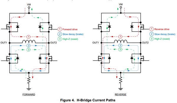
    We know that motor is inductive device, can you teach me how to protect against EMI please? I'm not sure whether the green line in figure4 helpful or not.

  • Hi Lin,

    Please see the link 

    You can also find this at the top of the motor driver forum and to the right in the FAQ section. 

  • Hi rick

    Sory for misleading you. I mean back EMF instead of EMI.

    We know that motor is inductive device, can you teach me how to protect against back EMF please? I'm not sure whether the green line in figure4 helpful or not.

  • Hi Lin,

    Yes, the green line is helpful.

    But you need enough capacitance to prevent the VM voltage from increasing above the absolute maximum of the DRV8872-Q1 and any other device connected to VM.

    Section 9 of the datasheet provides general guidelines. The link previously provide also provides some recommendations regarding placement and vias.

  • hi rick

    Back EMF of my motor is tested with DRV8872EVM. Please fback EMF test.pdfind attachment and thanks!

  • hi Rick

    Back EMF of my motor is tested with DRV8872EVM. Please find attachment and thanks!

    7002.back EMF test.pdf

  • Hi Lin,

    The -1V and VM+1 or 3V is not back EMF. This is the inductive spike required to keep flowing when the outputs are disabled.

    The current flows through the body diodes of the low or high side FET, which causes the outputs to be either slightly below ground or slightly above VM.

    When a series diode is inserted in the VM path, was the total capacitance on the DRV8872VM also changed? If so, the lower capacitance on VM causes the VM voltage to rise more than with the original capacitance.

    To see the back EMF, please refer to the link below.


  • Hi rick

    The article you recommended has been carefully studied. Two key points are illustrated:

    First, three resistors are added to limit ADC voltage to 3.14V. (This 3.14V is calculated when voltages of out1 and out2 are -0.7V and 11.7V, respectively. Namely, current is flowing through body diode.)

    Second, back emf should be tested within 1ms after driver enters hi-Z.

    Similarly, my -1V and VM+1 is tested when current flows through body diode and driver enters hi-Z immediately. I think they should be emf. Please correct me and thanks.

    BTW, when a series diode is inserted in the VM path, only this series diode is added between precious power suppy and DRV8872EVM. I think total capacitance should not be changed. And I cannot understand this result. Thanks again for your warm help.

  • Hi Lin,

    Second, back emf should be tested within 1ms after driver enters hi-Z.


    Back EMF should be tested after the current has dissipated. This can take a few microseconds or milliseconds depending on the motor.

    Similarly, my -1V and VM+1 is tested when current flows through body diode and driver enters hi-Z immediately. I think they should be emf. Please correct me and thanks.


    The -1V and VM + 1V  is the inductive spike needed for the current to flow through the body diodes. This same spike can be seen in an inductor.

    BTW, when a series diode is inserted in the VM path, only this series diode is added between precious power suppy and DRV8872EVM. I think total capacitance should not be changed. And I cannot understand this result. Thanks again for your warm help.


    If you have not changed the capacitance value on the EVM, adding the series diode should have not impact on the operation.

  • Hi Rick

    Updated my latest test result.

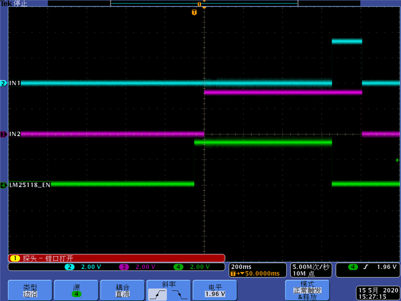
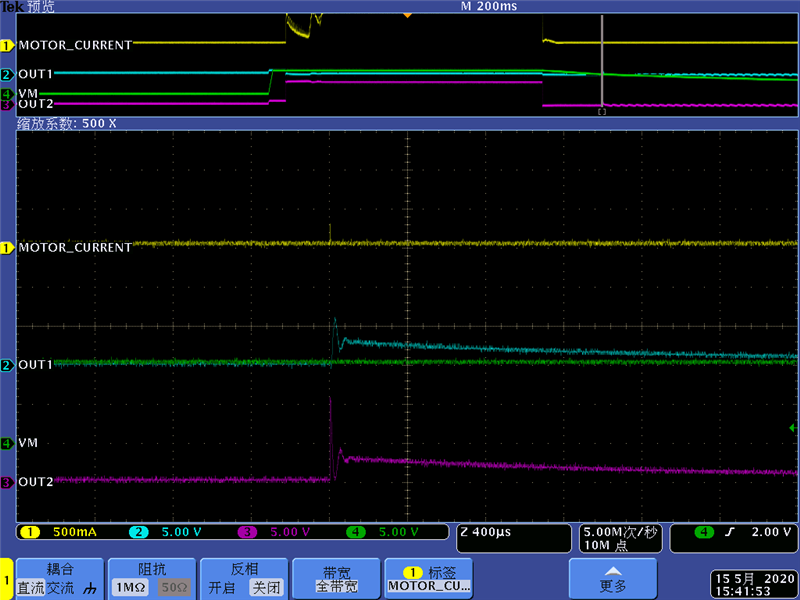
    When IN1=0 and IN2=1(approx. 640ms), my motor moves forward. When IN1=1 and IN2=1(approx. 150ms), my motor stopped and two LS-FET is used to decay motor current. Can I draw a conclusion that "when motor current decreased to zero, no back emf is produced"?

  • Hi Lin,

    Can I draw a conclusion that "when motor current decreased to zero, no back emf is produced"?

    Once the motor current decreases to zero, the Back EMF is produced if the motor is moving.

  • Hi Rick

    For my application, 640ms is used to move my motor forward. Actually, 250ms is enough for my motor to finish this forward request.

    Namely, my motor has stopped for 640-250+150=490ms, when current decreases to 0. No back emf is produced because when current decreases to 0, motor has stopped for a long time.

    This also corresponds with your explnation: "Once the motor current decreases to zero, the Back EMF is produced if the motor is moving."

    Am I understand it right? Thanks for your warm help.

  • Hi Lin,

    In the last image posted above, it appears there is some ripple on both OUT1 and OUT2 in the non-zoomed section of the image.

    If the motor is coasting to a stop at this time, that is Back EMF. If the motor is stopped that is could be noise on the probes.

    Please measure the OUT1/OUT2 voltages when both outputs are Hi-Z and the motor is not moving.