This thread has been locked.

If you have a related question, please click the "Ask a related question" button in the top right corner. The newly created question will be automatically linked to this question.

DRV8304: Is it correct to have constant Voltage on SHx Pin about 13,6 Volt?

Part Number: DRV8304

Hi,

I try to make a project with drv8304 and I have soldered the drv8304 but without the mosfets, I tested if SPI communication is working and now I want to solder the mosfet to start build my project step by step.

I measured without the Mosfet a voltage on SHx Pins about 13,6 volt. The device is configured as 3xPWM Mode and now I am not sure if the device working properly.

I supply the device with 11 Volts, is it correct to have voltage on SHx pins or maybe the device is destroyed during soldering?

Thanks in advance,

Nikos

  • Nikos,

    Thanks for posting on the MD forum!

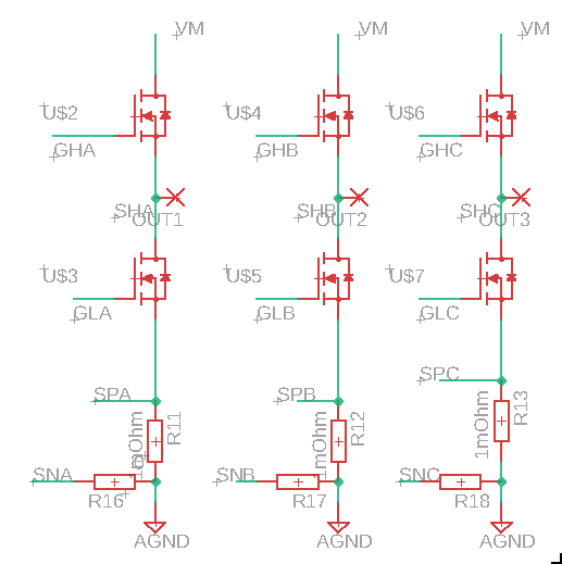
    Could you show us a diagram or schematic showing exactly which components you have fitted on your PCB?

    Are you switching the INHx/INLx inputs? Can you check GHx and GLx at the same time?

    Regards,

    -Adam

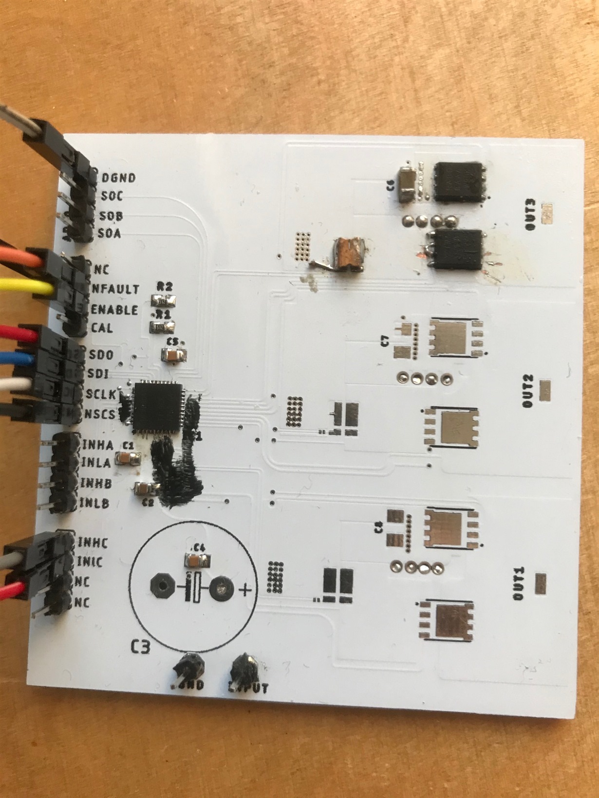
  • Thank you for your reply, lets see all the information that I have. My PCB is very ugly because was very difficult to solder the ICs with solder iron, sorry for that.

    First of all, I use 3xPWM Mode and i have the following task, every 500ms. I fixed the INLC pin to HIGH and toggle the INHC every 500ms.

    /* USER CODE END Header_testTask500msFunc */
    void testTask500msFunc(void *argument)
    {
      /* USER CODE BEGIN testTask500msFunc */
      portTickType xLastWakeTime;
      const portTickType xDelay = 500 / portTICK_RATE_MS;
      // Initialise the xLastWakeTime variable with the current time.
      xLastWakeTime = xTaskGetTickCount ();
      /* Infinite loop */
      for(;;)
      {
    	  uint16_t intermediateVar[2]={0,0};
    	  MX_DRV8304_Request_Status(intermediateVar,&hdrv8304);
    	  HAL_GPIO_WritePin(GPIOB,DRV_INLC_Pin, GPIO_PIN_SET);
    	  HAL_GPIO_TogglePin(GPIOB,DRV_INHC_Pin);
    
    	  // Wait for the next cycle.
    	  vTaskDelayUntil( &xLastWakeTime, xDelay );
    
      }
      /* USER CODE END testTask500msFunc */
    }

    R16,17,18 are 0 Ohm, like jumpers.

    As you can see on the picture, I drive only Mosfet C. I measured the following voltages:

    According to ground and VM =11 Volt
    GHC : Toggles between 20 Volt and 14 Volt.
    GLC : fixed to 0.75 Volt
    GHB: fixed to 13,7
    GLB: fixed to 0.75
    GHA: fixed to 13,8
    GLA: fixed to 0,75
    SHC: fixed to 11,6
    SHB: fixed to 13,7
    SHA: fixed to 13,8
    Nfault stays high

    }

  • Nikos,

    I don't see any issue here. Phase C is switching fine. The high side FETs of phases A and B are OFF which can be seen by their SH node being equal to their GH node. When SHx is equal to GHx the gate-to-source voltage of the FET is 0V and therefore the FET is off. It is normal to see some voltage on SHx/GHx when the FET is off because of small leakage in the device which is due to it's architecture. The leakage path is only ~200uA and will dissipate once the low side of that phase turns on.

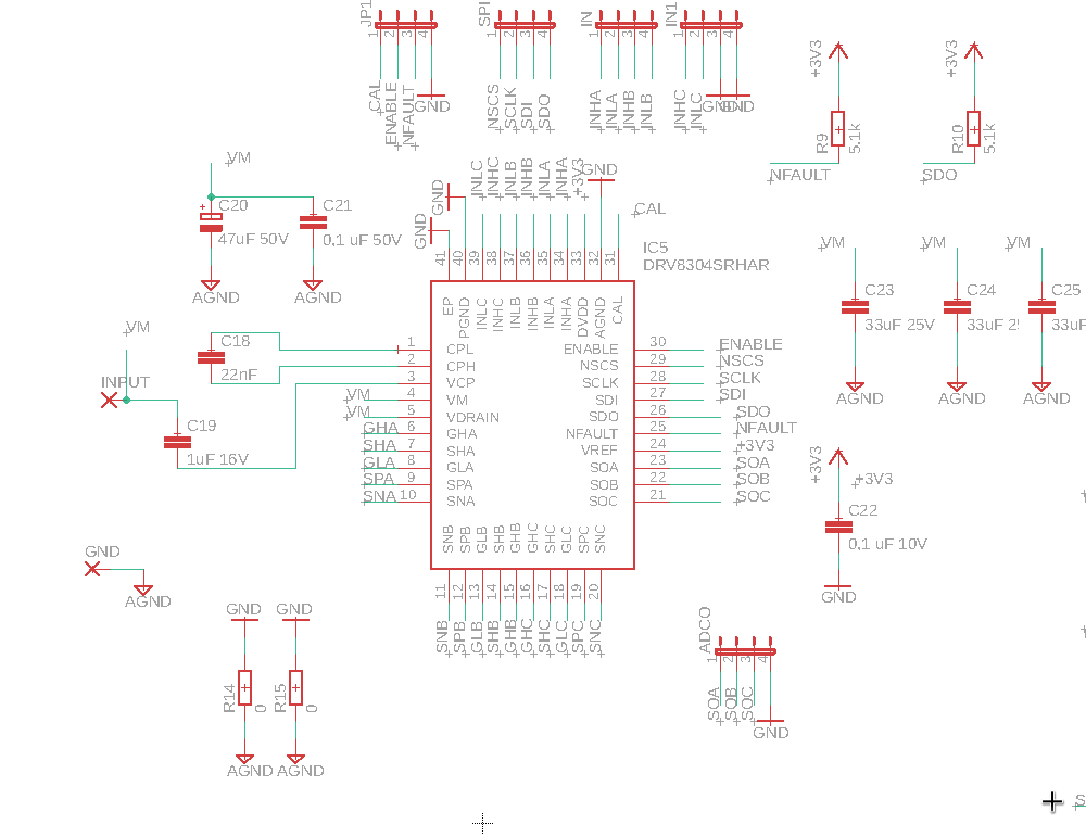
    This being said I would like to review the rest of your schematic if you can share the circuit surrounding the DRV.

    Regards,

    -Adam

  • Hi and thank you for the rapid answer,

    I am confused, because you said switching is fine. According the datasheet, if I fixed my INLC Pin high and toggle the INHC Pin, I should see in SHC a voltage

    between VM=11V and Null Volt but I can see only the VM. The GLC is also fixed to 0,75 Volt, that seems to me that the low side Mosfet is not turning on.

    Am I wrong?

    This is the schematic around the drv8304.

    Thanks in advance,

    Nikos

  • Nikos,

    What are you using to measure the SHC node and GHL node?

    If it is a multimeter then it may be too slow to see the switching waveforms and you would only see an average voltage which appears somewhere between the min and max of the switching voltages.

    Regards,

    -Adam

  • Hi,

    I am using also an oscilloscope, but the waveform is linear on SHC and GHL.

    I am not sure, if the FET is from Soldering defect but then there is two questions, should be changed the VGL if the FET is defect? and why the DRV8304 cannot see the failure? If otherwise FET is ok, Why the VGL is constant at 0,75 Volt? 

  • This is the measurement from VGH

    This is from SHC, the voltages are 14 Volt and 13.3 Volt but I have VM 11 ?? That is strange to me.

    And this is GHL fixed to 0,75 Volt.

    Regards,

    Nikos

  • Hi,

    I have soldered a new one PCB and now the Half Bridge C is working fine. I think something was defect in the other drv8304.