


Other Parts Discussed in Thread: DRV8308
Hi,
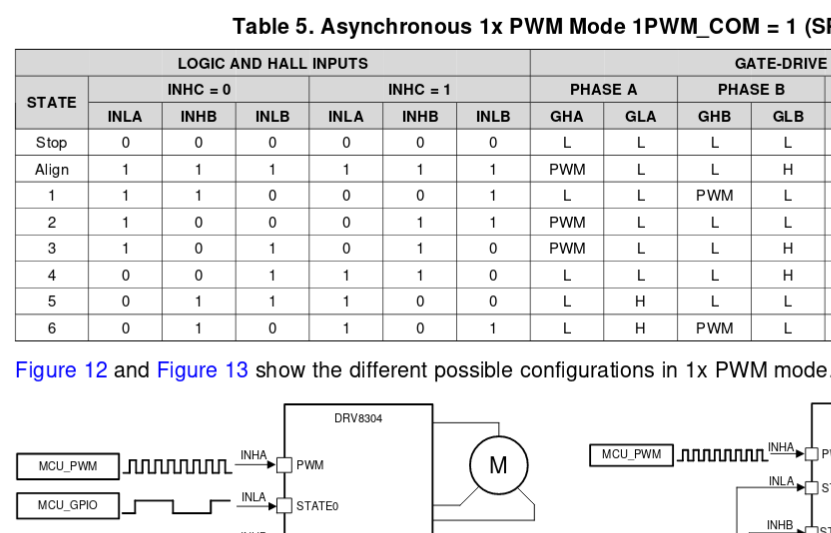
I use the DRV8304 to 1xPWM Mode Asynchronous and I use the following code to change every 500ms between state 1 -> 2 and 2 ->1:
__HAL_TIM_SET_COMPARE(&htim4,TIM_CHANNEL_1,(uint16_t)900); //INHA PWM Signal ca. 5KHZ
HAL_GPIO_WritePin(GPIOB,DRV_INLA_Pin, GPIO_PIN_SET); //INLA set High
HAL_GPIO_WritePin(GPIOB,DRV_INLB_Pin, GPIO_PIN_RESET); //INLB set Low
HAL_GPIO_TogglePin(GPIOB,DRV_INHB_Pin); //INHB Toggle every 500ms
I applied the Oscilloscope on VGHB and VGHA and on the VHGA is applied the PWM Signal and on the VGHB is not applied a PWM Signal.
VGHB:
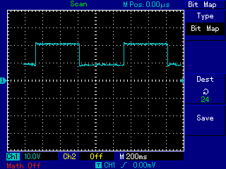
VGHA:

According to datasheet, if I applied the PWM signal on INHA Pin then is available to all VGHx pins.
Could someone explain me what is going wrong?
King Regards,
Nikos

