This thread has been locked.

If you have a related question, please click the "Ask a related question" button in the top right corner. The newly created question will be automatically linked to this question.

DRV10963AEVM: DRV10963 chip brushless motor startup problem

Part Number: DRV10963AEVM
Other Parts Discussed in Thread: DRV10963, DRV10983, DRV10974, USB2ANY, DRV10987

Hi Team,

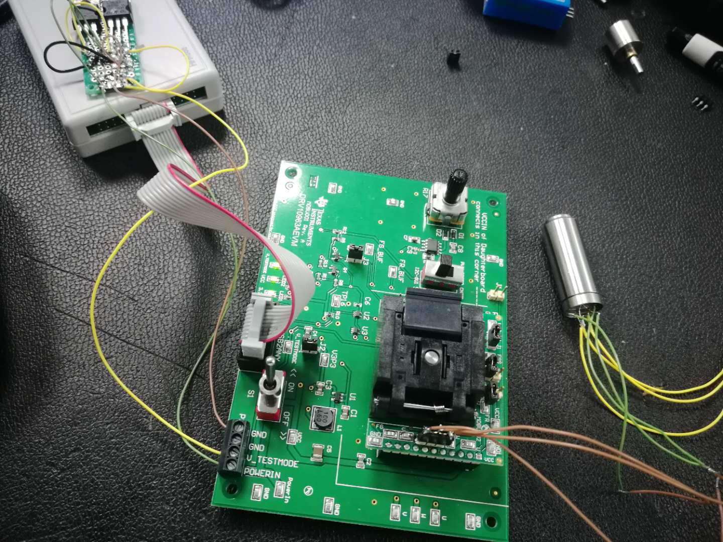
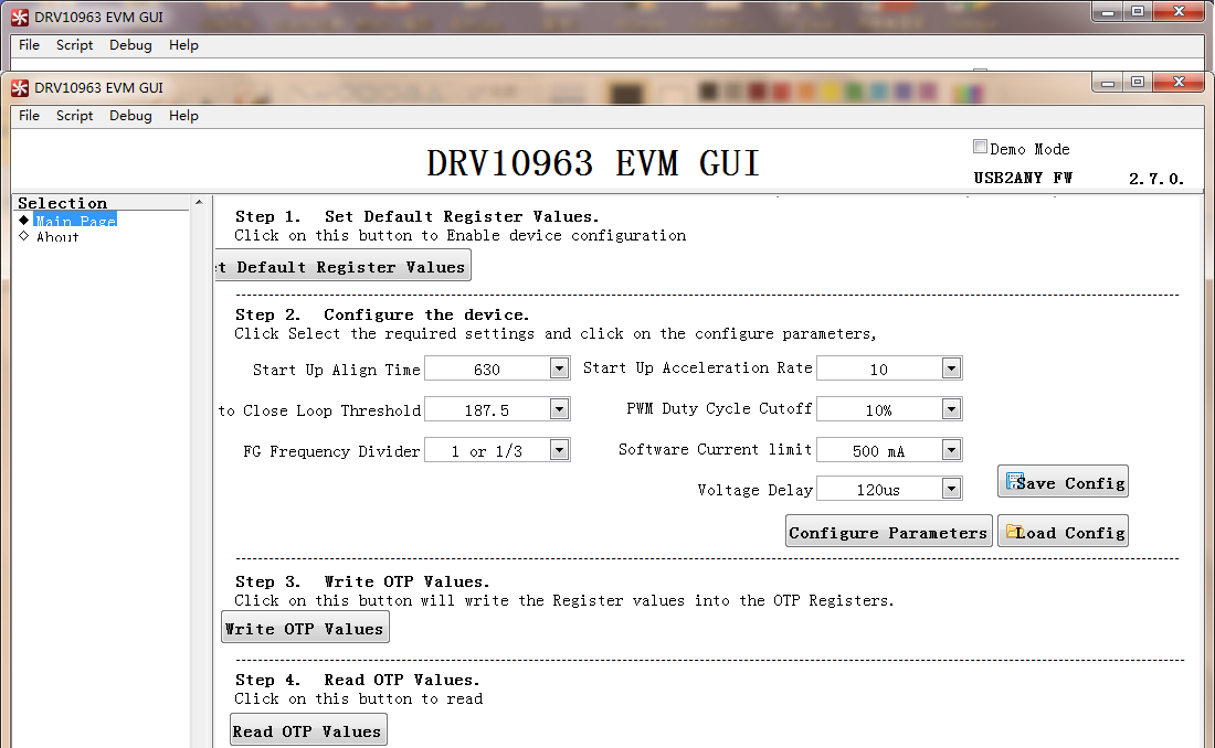
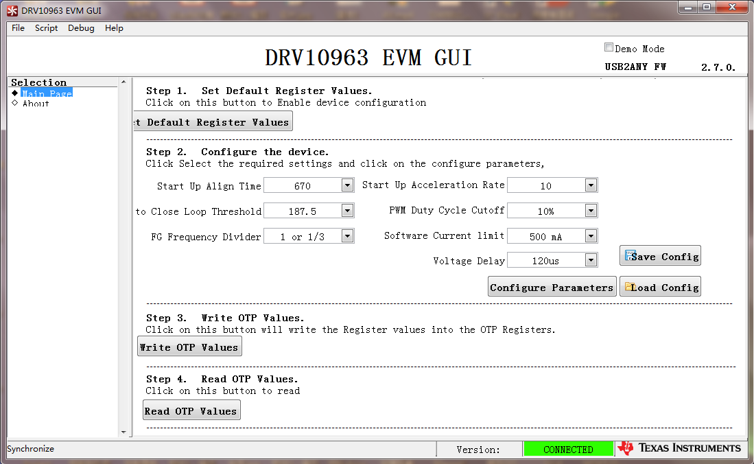
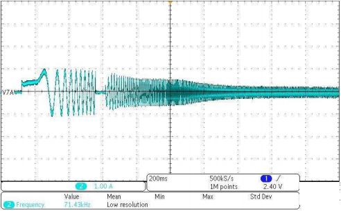
The customer is developing an integrated brushless motor. He used DRV10963AEVM to drive, and the motor started intermittently. 

He measured with an LRC bridge:

  • Brushless motor phase resistance is 6.2 ohms
  • Phase-to-phase inductance is around 86

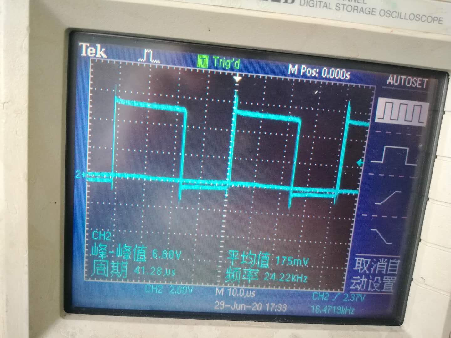
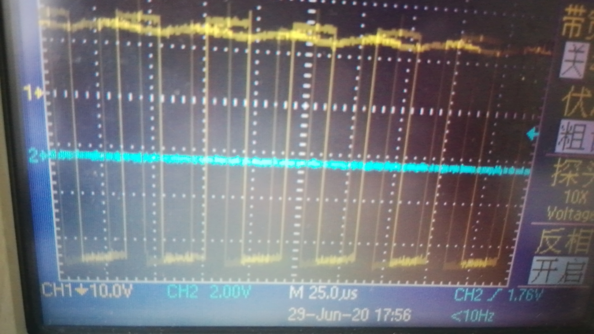
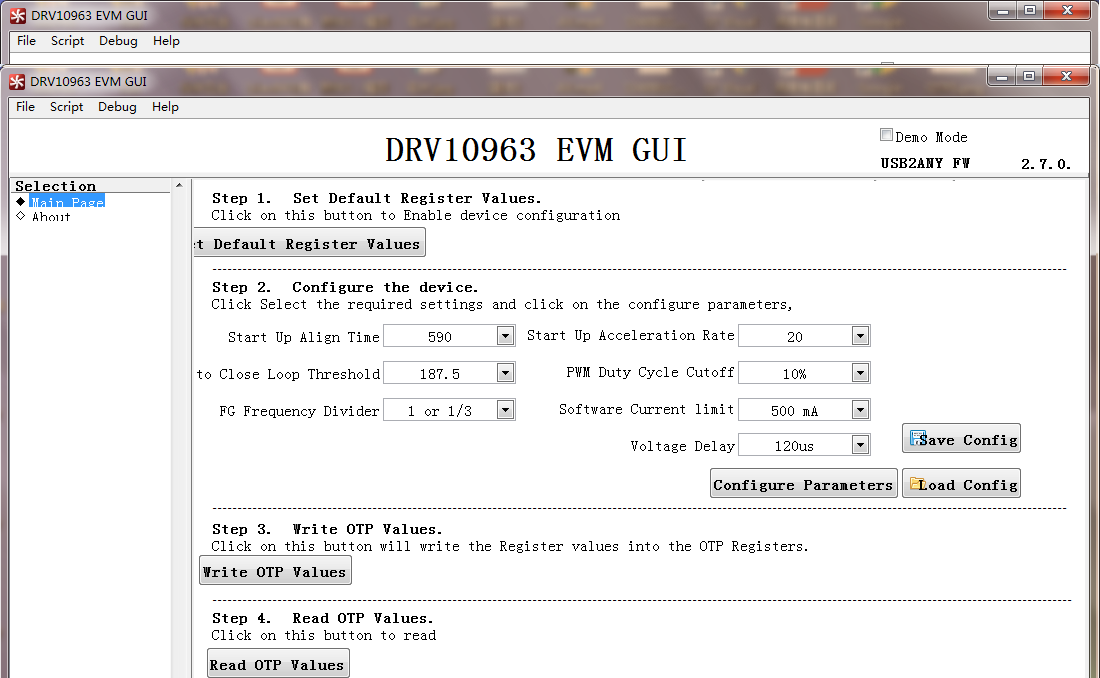
No matter how the software is adjusted, the brushless motor still cannot run normally. Would you kindly help to check the reason?

Thanks,

Annie

  • Please consult us about the failure of DRV10963 motor in normal operation. We hope American TI engineers can provide technical support.This case is the project I am developing. Yesterday, I rewound the wire. The resistance of the coil is 3.8 ohms.The inductance is 60uh. I have almost used up all the methods of DRV10963AEVM and still can't start the brushless motor properly.Please tell me what I should do.

    Annie Liu said:

    零件编号: DRV10963AEVM

    嗨,团队,

    客户正在开发集成的无刷电机。他使用DRV10963AEVM进行驱动,然后电动机间歇性启动。 

    他用LRC桥测量:

    • 无刷电机相电阻为6.2欧姆
    • 相间电感约为86

    无论软件如何调整,无刷电机仍无法正常运行。您能帮忙检查一下原因吗?

    谢谢,

    安妮

  • Hi Annie,

    Thanks for posting your question in MD forum.Its a little tough understand what the problem might exactly be without more info. Is the 60 uH phase to phase or phase to center tap? What is the BEMF constant Kt of the motor? Was the customer able to communicate to the EVM using the GUI? Can you share the OTP settings of the device?  Also can the customer provide a scope plot of the voltage and current of the 3 phases when they start the motor? 

    Regards,

    Vishnu

  • Glad to receive your answer, the first coil is interphase inductor 82UH, the second coil is Y type connection center inductor 60uh. Gui-evm communication seems to often go wrong.EVM power is now 6.7V and 5.0V, and each time you press Configure Parameters, an error will appear.Please guide me where I went wrong?How do I do guI-EVM communication?

  • Hi,

    Looks like there is an issue while writing values to the register. I would highly recommend checking the step by step process documented in the DRV10963EVM User Guide. The EVM should be in test mode (5V supply ON and Jumper J1 shorted on motherboard) when you write values to the shadow register. Please refer ti Chapter 5.5 in the User guide for more information.

    Regards,

    Vishnu.

  • Hi Vishnu, I have made further tests through debugging.At present, the motor can work for 30 seconds before it stops. I have created a new motor coil to increase the inductance. I am trying to change the current to make DRV10963 reduce the heat.Please direct the motor to stop for 30 seconds. Is there still a problem with chip heating protection or OTP setting?

  • Was Mr. Vishnu's GUI configuration test run correctly with 15-30 seconds of downtime?Or is my setup still a problem?

    • Unable to find the positive porch wave. What's the reason?

    • Unable to find the positive porch wave. What's the reason?

  • Hi,

    I'm not sure what these waveform represent. Can you share the phase current waveform of the motor?

    Regards,

    Vishnu

  • Hi, I'm Jiang Cheng in Shenzhen,
    China.Before, I asked for help with
    the starting of DRV10963 motor and got help from
    a gentleman in the technical forum. Thank you very much.I still
    have a problem: after GUI programming, the brushless motor will stop
    and restart after 30S.I experimented with all of FUI's methods.It's better not to run successfully yet, because inside the GUI test seat I think it's chip heat that stops running.Please ask TI USA to give support.China's dental industry is in desperate need of such a motor.Of course, my chip choice is TI DRV10963. So I continue to seek support from engineers.thank you

  • Hi,

    The waveform that you shared looks like the Icc (supply current). Since your motor is restarting after 30 sec, this gives an indication that there is a startup issue. Can you share the OTP settings and the phase current waveform?

    Regards,

    Vishnu

  • OTP1 set the motor to run for 30 seconds, stop and restart.OTP2 set the motor to run for 20 seconds, stop and restart.OTP3 Set motor restart for 10 seconds.Wish you good health and happy every day.

  • Hi,

    Can you please try increasing the Software current limit and the Startup acceleration rate?

    Regards,

    Vishnu

    • How does the software increase current? How to increase the acceleration rate?  Have a good day at work.

  • . I have conducted a variety of experiments. The current working current of the motor is 100MA-110ma.I adjusted the software current to 875mA, but the motor still could not work normally.I remove the motor from the normal drive motor and it will work smoothly.The continuous operation of 12V was up to 19800RPM, but I could not find any problem with the motor. The best Japanese material of 0.1 thickness was used for the silicon steel sheet, and the magnet was also the best.Is it because of the high motor power that DRV10963EVM cannot bear the load?Or running a program incorrectly.I see that the DRV10963 data shows a supported frequency of 1300HZ.I calculate that the current speed of the motor is 8000RPM.So we're just working at 133HZ.No positive wave voltage to motor input is seen.Again, please help guide...I wish you good health and peace

  • You mentioned the maximum speed is 133 Hz but you have set the open to closed loop threshold frequency to 187.5 Hz. Can you decrease the open to closed loop threshold frequency to 25 Hz or 37.5 Hz?

    Regards,

    Vishnu

  • I have found the problem, which is the brushless motor. I made a new rotor and the result will be available soon

  • Hi!

    Good to know. 

    If your issue has been resolved, please help us out by clicking the green “This Resolved My Issue” button.
    If you have a related question, please use the orange "Ask a related question" in the top right corner of the page.

    Regards,

    Vishnu

  • HI, the new rotor was finished today. I changed the diameter of the original rotor from 6.5 to 5.0. After core installation, I found that the motor was still the same problem.I want to point out that the rotor has been reduced from 64 grams to 36 grams.I'm still confused and can't find the problem.I have a question: is DRV10963 stable or not.As for the motor not working continuously, I wonder if there is a thermal shutdown when DRV10963 is installed in the test seat?Looking forward to your guidance

  • Hi,

    I don't think this is a thermal issue. Can you share the motor phase current waveform along with the RMS current value? I'm looking for a plot that looks something like the one shown  below. As recommended in my previous posts, did you try decreasing the open to closed loop threshold frequency? When open to closed loop threshold is set above the max electrical frequency of the motor, then the device will stay in open loop and the motor will draw more current.


    Regards,

    Vishnu

  • HI, I handed the DRV10963 project to my friend in Shanghai. What is the reason for his frequent errors in using GUI setting DRV10963 in installation?

  • I'm not sure what "frequent errors" you are mentioning here? Can you provide more details about the frequent error you are talking about?

  • Thank you very much for your support. I really have no way to make the motor run smoothly.My client is urging me to succeed in debugging as soon as possible. They want to use it in dental tools and equipment, so they need to start quickly and change direction quickly, so I am looking forward to your technical support. I am sending it to my friend in Shanghai, who is a senior engineer, and I hope he can improve the program or help me succeed in debugging.I would be interested to know if there is a version of the DRV1093 chip that has been tuned to support more brushless motors.Looking forward to your reply. Thank you and good luck

  • Hi!

    I would recommend you to try DRV10983 and DRV10974. Both these devices have advanced features compared to DRV10963 and more tuning parameters.

    Regards,

    Vishnu

  • Hello, i did more test w/ the DRV10963 and I'd like to ask your help to share when the DRV10963 will stop driving motor and spin the motor again in few seconds

    Here is what i did

    1) Use GUI to load the default config and set the Open to close Loop Threshold to 50

    2) Open J1, then the motor will start working. DRV10963 did spin the motor. 

    3) however, the motor will stop in couple of seconds (depending on the setting of the Start Up Align Time & Start Up Acceleration Rate).

    Could you pls help share some idea why the motor will stop then re-spin the motor? Thanks!

  • Hi!

    The device is triggering some fault and stopping the motor. After lock time, the device tries to restart the motor. This is a tuning issue. Can you share the current waveform of  one of the motor phases? I would highly recommend you to look into section 6 in the EVM Tuning guide for detailed information on tuning the device parameters.

    Regards,

    Vishnu.

  • HI  Vishnu

    The DRV 10963EVM motherboard already has 555 circuit to produce PWM signal, why is it connected externally with 50KH square wave signal, does the PWM on motherboard need to be disconnected?Outside access 50KHz square wave motor will certainly run?Would you also like to know that the actual driving power of DRV10963 can reach the demand of 4W motor?

    Wish you a pleasant work and good health

  • 6.1.6 Control Advance Angle Method a.k.a Voltage Delay
    Voltage delay represents lagging phase angle (in unit of time) of back-emf with respect to applied voltage.
    As explained in the datasheet, for efficient operation, applied voltage must lead the back-emf to force the
    motor-current in phase with back-emf for constant air-gap BLDC moor without saliency. For salient pole
    motors back-emf and phase current may have phase angle difference for efficient operation depending
    upon motor parameters. Both types of motor can be tuned efficiently via the GUI using voltage delay. In
    the GUI, zero delay setting forces the applied voltage in phase with back-emf and increasing its value,
    make the applied voltage to lead with respect to back-emf. To determine the optimized value, run the
    motor at rated speed as per end-application requirement and adjust the value to draw minimum current
    from the power supply.
    1. Configure the motor using the Tuning Guide up to this point and make sure it can spin in closed loop
    control (after the current flat lines on startup and then keeps oscillating). Switch S2 to the PWM so it
    can receive a PWM signal. Have a current probe on one of the phases of the motor and a voltage
    probe on the FG pin of the daughterboard. Also make sure that the input voltage VIN is run through a
    multimeter so that you can know the exact output current at all times.
    2. Change the Voltage Delay to “No Delay” and click ‘Configure Parameters’.
    3. Next, the device must be taken out of test mode. Disconnect the USB2ANY from the EVM board. Turn
    off the output of 6.2 V. Disconnect the J2 jumper from the motherboard.
    4. Connect a function generator to the PWM in the pin located on the daughterboard. The function
    generator is outputting 50 kHz square wave at 5 Vpp with 2.5 V DC offset and in High Z. Using this
    signal, adjust the duty cycle to reach the RPM that is desired for your application. The RPM can be
    obtained using Equation 1. The frequency of the FG pin corresponds to the electrical frequency.
    (1)
    5. Take the current measure from the multimeter.
    6. Once you have those taken down, turn off the output of the function generator and do the steps in
    reverse order to put the device back into test mode. Connect J2 and the USB2ANY and then turn on
    the 6.2-V supply.
    7. Reopen the GUI, connect to the device and set the default register values like in the tuning guide.
    Next, configure all other values to what they were when the motor was spinning in closed loop.
    8. Repeat Steps 2-7 several times changing the "Voltage Delay" each time to get a few reference points.
    9. The "Voltage Delay" value that has the smallest current off of the multimeter is the current that is most
    in phase with the BEMF.
    If you are deciding between the JA and the JJ models, just do Steps 4 and 5 for both parts and pick the
    one with the minimum current between the two.

  • Hi,

    I'm not sure which 50 kHz square wave signal you are referring to. DRV10963EVM has a 555 timer to generate PWM pulses by comparing the saw tooth wave signal with the analog (pot) signal. This is required to control the speed of the motor. DRV10963 operates at max 5.5V and can provide Continuous winding current of 500 mA so it cannot drive a 4W motor. Please check DRV10983 and DRV10987 to meet your motor specification.  

    Regards,

    Vishnu.

  • 谢谢您的答复,我昨天做了一个实验,电机轴扭死案例DRV10963仍然驱动电机,能感觉到电机的振动,我按照6.16 PWM50KHZ的指导进行了实验,同时我们可以控制电动机的启动和关闭,但电动机仍然不可持续,并在调试模式下运行时,如果我认为感应电动势中没有问题,这是我第一次制造电动机。DRV10963是否要求电机绕组按180度分布?目前,电机是用空心杯缠绕的,或者由于DRV10963的高功率而根本无法驱动。不能在DRV10963上运行。我将使用DRV10987。983驱动22MM医用电机。我会尽快进行实验。DRV10963无法调试,原因未找到。请给予更多指导。

  • Hi!

    I don't understand what you mean by twisting the motor. 50 kHz PWM frequency is the driver switching frequency and not to be confused with 25 kHz PWM input frequency which is used to set the speed command in PWM mode. Sorry we cannot comment on motor design as we are not the experts. I still believe we cannot drive a 4W motor using DRV10963. What is the rated current of the motor?

    Regards,

    Vishnu.