This thread has been locked.

If you have a related question, please click the "Ask a related question" button in the top right corner. The newly created question will be automatically linked to this question.

DRV2625: About DRV2625 resonance frequency

Part Number: DRV2625

Hi TI,

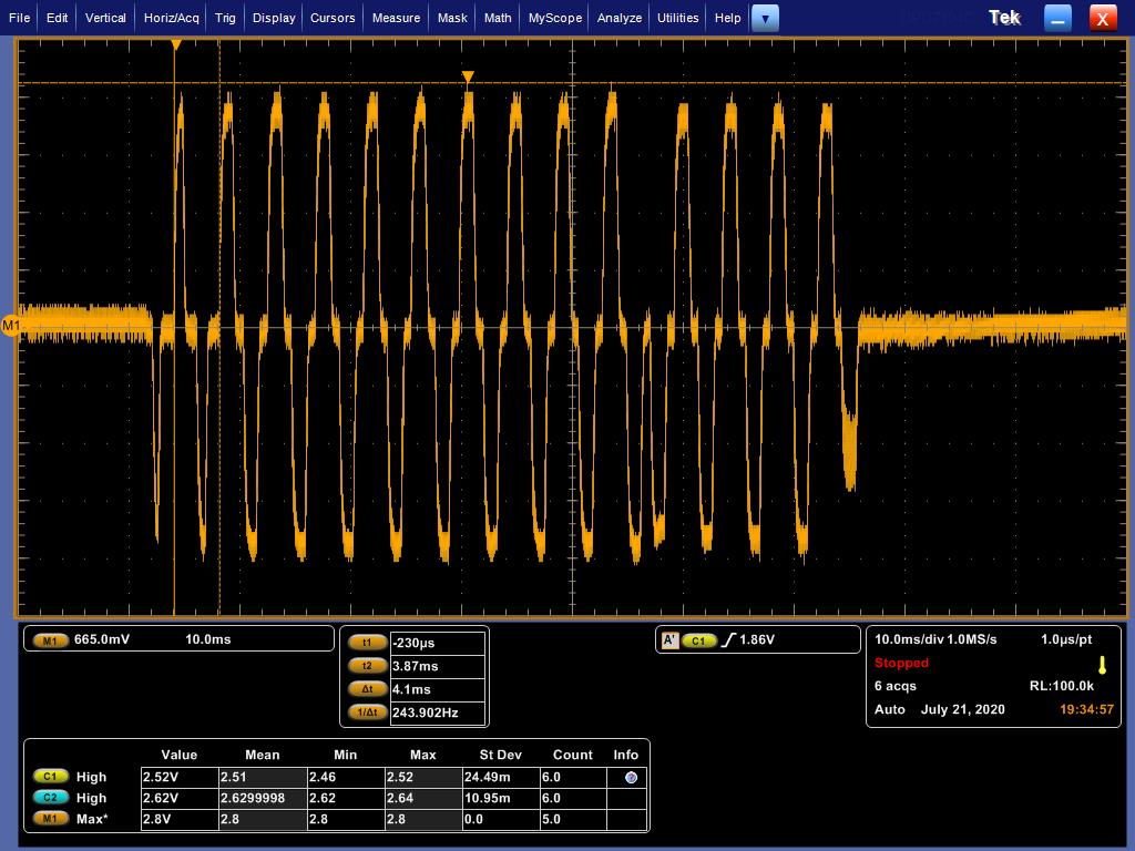
We use TI DRV2625 hatic IC and measured the vibrator waveform as below


The frequency is faster at first (~425Hz), then slower (~232Hz).The slower frequency is near the resonance frequency of the vibrator we used.
Is this behavior normal for LRA? Is the faster frequency the resonance frequency of the tracing LRA at the beginning?

Thank you!

Scott

  • Hey Scott,

    I am looking into why this high frequency output is initially occurring, but could you tell me is this happening every time you play any waveform or just after you power on the device and play a waveform for the first time?

    It is natural for the auto-resonance tracking to adjust to the exact frequency of the attached LRA when first driving it after being powered on, how quickly the resonant frequency takes to lock on to the exact value depends on the DRIVE_TIME parameter in register 0x27 which may have an effect on this recording if changed according to the description on page 54 of the DRV2625 datasheet.

    Also just to be sure, are you running the auto-calibration routine before playing this waveform and taking the recording?

    Best Regards,

    Carson Allen

    LPAA Applications

  • Hi Carson,

    We ensure that we conducted the auto-calibration before playing the waveform.

    In addition, the previous experiment 's vibrator was not fixed. Thus we try to fixed it and measure it.It's seems the most frequency is normal.

    I would like to ask two questions:

    1.If the vibrator is not fixed, will cause resonance-frequency tracking fail or even auto-calibration fail at initial setup?

    2.Below are the waveform we use fixed method.But why the first of waveform always seems a little higher frequency than f0.(our f0 is 235Hz)

    Also we found the Fig.6 in datasheet seem have similar situation.

    Thank you!

    Scott

  • Hey Scott,

    1. If the actuator is not fixed and is able to move in place it will throw resonant tracking off and cause it to take longer to lock on to the exact resonant frequency of the device. Auto-calibration would not fail because it is just try to compensate for resistive losses and adjust back-EMF gain and does not calibrate the resonant tracking.

    2. The frequency is always a little higher in this case because the device starts driving the LRA based on the setting of the DRIVE_TIME[4:0] parameter in register 0x27 before the resonant tracking is able to lock onto the exact frequency. The default value of that parameter if you look on page 54 of the datasheet corresponds to trying to drive a frequency of a little over 238Hz which is a little above your exact frequency of 235Hz. If you are unhappy with this initial faster frequency, I would suggest trying to change the DRIVE_TIME[4:0] according to its description.

    Best,

    Carson

  • Hi Carson,

    Thank for your reply! It's helpful.Actually we also use the drv2625 configuration tool to check the available setting.

    We already set the Rated Voltage, Overdrive Clamp, and Drive Time in the auto-calibration section as well as Rated Voltage, Overdrive Clamp,Mode in the initialize section.Could you tell me what else configuration should we set?Our expectation is using 235Hz vibration and would like to through MCU to give a trigger to control the favorite waveform which is from waveform library.

    In addition, we also provide the configuration file we set, I would be appreciate it if you could help us to check other setting.

    Thank you!

    Best Regards,

    ScottDRV2624 and DRV2625 Configuration Tool and Design Equations-AWA.xlsx

  • Hey Scott,

    To have the device function as you are describing

    I would make sure to set:

    TRIG_PIN_FUNC = 0 for external pulse trigger in all sections

    MODE = 1 for waveform sequencer mode in all sections

    WAV_FRM_SEQ1 = To the ID of the favorite waveform you want to play

    LRA_ERM = 1 for LRA in all sections

    CONTROL_LOOP = 0 for Closed-Loop Operation in all sections

    and use the WAV_SEQ_LOOP parameters if you want this waveform to loop a certain number of times before going back to stand-by

    Also make sure the wire between the GPIO pin of your processor and the TRIG/INTZ pin does NOT have a pull-up resistor on it.

    Best,

    Carson

  • Hi Carson,

    Sorry I want to further explain what I have discussed. Actually we would like to use go bit though the I2C to give it a trigger, not for the external plug ones , what should I set If  in this condition?

    Thank you!

    Best Regards,

    Scott

  • Hey Scott,

    No problem.

    You should still just set TRIG_PIN_FUNC = 0 because the GO bit will still be able to be used. Just make sure not to set to 1 because that would disable the GO bit functionality.

    Best,

    Carson