This thread has been locked.

If you have a related question, please click the "Ask a related question" button in the top right corner. The newly created question will be automatically linked to this question.

DRV2625: DRV2625 measured waveform by different LRA setup

Part Number: DRV2625

Hi

What is the correct setup for LRA when measure waveform? Seems different setup will get different waveform

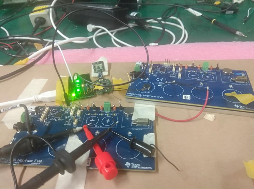
We use two setup, one is fix LRA(sticky LRA bot side on loading plate), the other is hold on hand with press the pad of LRA

We test waveform strong click 100% and soft bump 100%

Thank you~~

 fix LRA(sticky LRA bot side on loading plate),

hold on hand with press the pad of LRA

 strong click 100% -- fix LRA(sticky LRA bot side on loading plate),

 strong click 100% --hold on hand with press the pad of LRA

soft bump 100% -- fix LRA(sticky LRA bot side on loading plate),

soft bump 100% -- hold on hand with press the pad of LRA


  • Hey Poki,

    Something similar to the first way you mentioned and showed except you dont want to stick it to something with another LRA already on it, this is due to dampening caused by the other LRA and will alter the closed-loop feedback of the system. Also under whatever you stick the LRA you would want to put foam to isolate it from the rest of the table. Here is a picture of what the proper set-up of an external LRA:

    You could take off one of the pieces of metal from one of the EVMs you have and create this exact set up.

    Best,

    Carson Allen

    LPAA Applications

  • Hi Carson:

    Thanks for feedback soon

    Any good way tak off metal from EVM? the tape is very strong^^

  • Hi Carson:

    Or can we just remove this LRA that already on it?

    And the ERM can still on it?

    thank you~~

  • Hey Poki

    You can just remove the LRA that is already on it and Leave ERM

    Best,

    Carson

  • Hi Carson:

    OK, I will remove the LRA and re-test

    But can I know first that what the strong click 100% and soft bump 100% wavefrom look like?

    Is it similar to present fix LRA waveform? Or totally different due to other LRA on it?

    Or do you have this two waveform can provide?

    thank you~~

  • Hey Poki, 

    If you look on page 7/Figure 6 on DRV2625 Datasheet you will see what Strong Click is supposed to look like.The first waveform you provided resembles it and you can check to see if the voltage amplitudes match with your set overdrive clamp voltage for the overdrive portion and rated voltage for the lower middle portion.

    I will need to create a recording of my own for the soft bump and get back to you on that.

    Best,

    Carson

  • Here is what the soft bump should look like, which is what your fixed LRA soft bump recording looks like

  • Hi Carson:

    Thanks feedback

    I remove the original LRA on EVM with loading and the waveform are the same

    My waveform is looks like with datasheet page 7/Figure 6 and you provided

    But there is still a little different, do you know why? And is it acceptable?

    Thank kyou~~

    Poki

  • Hey Poki,

    The Datasheet and my recordings used a different LRA than you are using which also means we are using a different rated voltage, clamp voltage, and operating frequency. This would account for any differences in the recordings besides just testing environment and actuator variance which is fine, as long as the haptic effect you feel is what is desired there is no requirement to perfectly match the recordings provided.

    Best,

    Carson

  • Hi Carson:

    I found a strange situation

    We use the same setup to measure again, but the waveform become unstable

    Could it come from measurement error? Or the driving waveform really become unstable?

    Could you provide some recommand for me to do test?

    Thank you~~

  • Hey,

    I am sorry to hear you are having trouble again.

    Could you provide a screenshot of the waveform recording so I can get a better understanding of how it is becoming unstable?

    What changed between last time and this time you do test?

    Best,

    Carson

  • Hi Carson:

    After exchange to another PCB, the waveform become stable

    So I test three PCB, one waveform is stable, one is a little unstable, and one is huge unstable

    I attached huge unstable PCB measured waveforms as below (waveform is strong click 100%)

    We check the REG pin voltage is normal 1.8V

    Any other thing that we can check?

    Thank you~~

    Haptic SCH, the green word "NM" mean no mount this element

    Also TRIG/INTZ pin we set it at low level

  • Hey Poki,

    I would suggest trying to change LRAs and see if the same results occur and then maybe change the board you are driving the LRA with if possible.

    Just try to test different combos of the driving DRV and the LRA themselves to see if these results persist.

    Otherwise maybe run the auto-calibration every time before testing to see if that makes a difference or run the diagnostics routine to see if it yields failed results

    Also try to run a waveform in open loop to see if the output result is more consistent, the resulting waveform will not look great but it will allow you to see if it can stay consistent and determine if the closed loop resonant tracking is the cause of these distortions. 

    Best,

    Carson

  • Hi Carson:

    We test 3 pcb with 3 LRA, the waveform pattern is strong click 100%, we find the unstable situation is follow PCB_EE9

      LRA1 LRA2 LRA3
    PCB_EE3 Stable Stable Stable
    PCB_EE7 Stable Stable Stable
    PCB_EE9 Unstable Unstable Unstable

    And below is PCB_EE9 with LRA1 waveform, the waveform change at the tail, not like the last time I reply to you with another PCB, last time PCB waveform is huge unstable, and PCB_EE9 is a little unstable

    Is it normal for last time huge unstable?

    Is it normal for this time little unstable?

    I also attach our DRV2625 setting excel file and LRA datasheet , please help check if anything wrong with our setting, thank you~~

    DRV2624 and DRV2625 Configuration Tool and Design Equations-AWA_modified.xlsx20200423 CZ-EACQ SPEC_Draft_AWA.PDF

  • Hey Poki

    It is not normal for the really unstable waveforms to happen as long as the LRA set-up is consistent. Some instability could be expected base on the stability of the LRA environment

    Also to be clear, is it a new DRV chip for every new PCB? If it is a different chip every time then the really unstable graphs may be caused by a faulty chip

    Using our DRV-ACC16 EVM to measure an acceleration waveform of the LRA viibration might be useful for this situation of testing to get consistent results. It could help you see how much this waveform instability effects the LRA acceleration stability and help you guage what a consistent haptic effect looks like.

    Best, an

    Carson

  • Hi Carson:

    Every PCB has it's own DRV2625, so the status follow IC

    But one thing interesting is the PCB_EE4 originally is hugh unstable, but today I test is stable, but at same setup environment, PCB_EE9 still unstable

    So do you think the unstable status is coming from setup environment? But just we don't know what the problem is?

    I attached our setup chart as below, Please help check

    Thank you~~

      LRA1 LRA2 LRA3
    PCB_EE3 Stable Stable Stable
    PCB_EE7 Stable Stable Stable
    PCB_EE9 Unstable Unstable Unstable
    PCB_EE4 @ 7/29 Huge unstable Huge unstable Huge unstable
    PCB_EE4 @ 7/31 Stable Stable Stable

  • Hey Poki, 

    The difference between the days for the PCB_EE4 was most likely due to some environmental change but the PCB_EE9's instability might be a result of a faulty chip or incorrect register setting. Lets try going into register 0x23 and adjust the FB_BRAKE_FACTOR and LOOP_GAIN parameters to lower values to see if it has an effect. I would also try doing the same for any that show instability to look for improvement.

    The picture above looks fine. I would try running PCB_EE9 in open loop and compare it to a open loop waveform of a stable one and see if they are the same, which they should be. This will let me know that if the auto-resonance is the source of the problem for that.

    Let me know how that goes

    Best,

    Carson

  • Hi Carson:

    1. I use the same setting for all tested pcb, so it mean EE9 is faulty chip? Or if we lower FB_BRAKE_FACTOR and LOOP_GAIN and all PCB become stable, it mean IC has tolerance?

    2. If you want to say --> I would try running PCB_EE9 in open loop and compare it to a "close" loop waveform of a stable one and see if they are the same

    Thank you~~

    Poki

  • Hey Poki,

    1.If EE9 is unstable there is a chance that it could be faulty with it's loop feedback and adjusting those parameters could lead to stability, and if that does work I would suggest doing that for the other chips as well to just enhance stability.

    2. I want to see two open loop waveforms compared, one from the EE9 and one from a PCB that has been consistently behaving normal.

    3. Also for these unstable waveforms have you measured the frequency and compared them to what it is supposed to be?

    Best,

    Carson