This thread has been locked.

If you have a related question, please click the "Ask a related question" button in the top right corner. The newly created question will be automatically linked to this question.

DRV8323: SPI write command issue

Genius 16285 points
Part Number: DRV8323
Other Parts Discussed in Thread: TMS320F280049C

Hi all 

My customer has below question for the DRV8323S, please comment and clarify.

Best regards

Ueli

--------------------------------------------------

We are currently facing an issue, when trying to write on the driver registers via SPI. 

Below the procedure that we followed.  Please note that the 3 « LOCK » bits located in Gate Drive HS Register are configured so that registers can be modified (011b).

Channel C1 : Chip Select

Channel C2 : Clock (300kHz)

Channel C3 : MOSI

Channel C4 : MISO


  1. Reading Gate Drive HS Register (adress 0x03) : we send 0x9800 on the bus


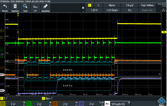
  1. Changing IDRIVEN_HS value from 2000mA (1111b, default value) to 1640mA (1110b) : we send 0x1bfe on the bus


  1. Reading modified Gate Drive HS Register : we send again 0x9800 on the bus à NO CHANGE (driver should have sent back 0x03fe)


Are we doing something wrong ? Any other lock bits to be configured ?


  • Hi Ueli,

    Thanks for posting to the MD forum!

    Could you try masking the LOCK and IDRIVEN_HS settings when writing to that register and try it one write at a time? For instance, could you unlock the registers in one SPI write command, then write the IDRIVEN_HS setting in a second write command? Let me know if that works. I'll inquire with the team for their thoughts on this. 

  • Hi Aaron

    Thank you for the quick reply. I have asked the customer to post his comments also in to forum to speed-up the process.

    Best regards

    Ueli

  • Hello Mr Barrera,

    I just did the manipulation, and no change at all. I can read registers but not write any of them...

    However, I did some other tests by my side and observed that the clock polarity could be in cause of this strange driver behavior.

    By changing this parameter (clock pin level low when idle) the driver seems to take writing command into account...but now the hexadecimal value sent by the master doesn't correspond to the value written on the SPI bus (everything is shifted by 1 bit) :

    1) clock polarity high when idle, as initally (reading driver registers ok but not writting).

    The master send 0x9800 to read the 0x03 driver register. Value on the bus correspond to the value sent by master.

    2) clock polarity low when idle (reading AND writting ok).

    The master send 0x9800 again. Value on the bus doesn't correspond to the value sent by master (one bit shift, seems like the first bit is missed).

    So clock pin level low when idle seem to be the right clock polarity configuration for the driver...Can you please confirm that ?

    Thanks,

    Best Regards

    Maxime WEY

  • Hi Maxime,

    Could you resend the post with the screenshots again? The screenshots didn't go through on your previous reply. Please use the "Insert File" command to upload from your computer. 

    Which MCU are you using for your SPI commands and initialization? Could you share your SPI initialization code?

    Typically you'll want clock polarity to be low so that SCLK is active high (transmit data on falling edge and receive data on rising edge).

  • Hello Mr Barrera,

    please find the previous screenshots below :

    - with clock polarity high when idle :

    - with clock polarity low when idle :

    Concerning the MCU, I use an STM32G4 with the following SPI configuration :

    - Clock phase : The first clock transition is the first data capture edge

    - Clock polarity : CK to 0 when idle

    - Master selection : MCU is the master

    - Baud rate control : fPCLK/256

    - Frame format : data is transmitted / received with the MSB first

    - Full-duplex mode

    -  SS output is enabled in master mode and when the SPI interface is enabled (Chip select)

    - NSS pulse : it allows the SPI to generate an NSS pulse between two consecutive data when doing continuous transfers. In the case of a single data transfer, it forces the NSS pin high level after the transfer

    - Motorola mode

    - Data size : 16 bits

    Thanks,

    Regards

    Maxime WEY

  • Hi Maxime,

    I cannot speak on behalf of the STM32G4 MCU since it is not a TI part. I can share with you SPI settings from code used to communicate with a typical DRV device using a TMS320F280049C (TI C2000 MCU). 

    Ensure your Baud rate is fast enough and that data is transmitted on the rising edge and received on the falling edge. 

    void Config_evm_spi(void)
    {
    //Pin Config
    EALLOW;
    // SPI_MOSI
    GPIO_SetupPinOptions(16, GPIO_INPUT, GPIO_ASYNC | GPIO_PULLUP);
    // SPI_MISO
    GPIO_SetupPinOptions(17, GPIO_INPUT, GPIO_ASYNC | GPIO_PULLUP);
    // SPI_CS
    GPIO_SetupPinOptions(56, GPIO_INPUT, GPIO_ASYNC | GPIO_PULLUP);
    // SPI_CLK
    GPIO_SetupPinOptions(57, GPIO_INPUT, GPIO_ASYNC | GPIO_PULLUP);

    GPIO_SetupPinMux(16, GPIO_MUX_CPU1, 1);
    GPIO_SetupPinMux(17, GPIO_MUX_CPU1, 1);
    GPIO_SetupPinMux(56, GPIO_MUX_CPU1, 1);
    GPIO_SetupPinMux(57, GPIO_MUX_CPU1, 1);
    EDIS;

    EALLOW;
    ClkCfgRegs.LOSPCP.all = 0;
    EDIS;

    // Initialize SPI FIFO registers
    SpiaRegs.SPIFFTX.all=0xE040;
    SpiaRegs.SPIFFRX.all=0x2044;
    SpiaRegs.SPIFFCT.all=0x0;

    //SPI Settings
    SpiaRegs.SPICCR.bit.SPISWRESET = 0; //SPI Reset On
    SpiaRegs.SPICCR.bit.CLKPOLARITY = 0; //SCLK Active High
    SpiaRegs.SPICCR.bit.SPICHAR = 0xF; //16-bit SPI char
    SpiaRegs.SPICCR.bit.SPILBK = 0;

    SpiaRegs.SPICTL.bit.OVERRUNINTENA = 0; //No overrun interrupt
    SpiaRegs.SPICTL.bit.CLK_PHASE = 0; //Phase 0
    SpiaRegs.SPICTL.bit.MASTER_SLAVE = 1; //Master mode
    SpiaRegs.SPICTL.bit.TALK = 1; //nSCS enabled
    SpiaRegs.SPICTL.bit.SPIINTENA = 0; //TX/RX Interrupt Disabled

    SpiaRegs.SPIBRR.bit.SPI_BIT_RATE = ((25000000 / 1000000) - 1); //Set baud rate to 1MHz
    SpiaRegs.SPIPRI.bit.FREE = 1; //Set so breakpoints don't disturb transmission
    SpiaRegs.SPICCR.bit.SPISWRESET = 1; //Exit SPI reset

    }

  • Thread closed offline.