Other Parts Discussed in Thread: DRV2624, DRV-ACC16-EVM
Achieving the right recording set-up is crucial in understanding the haptic effects produced by our haptic driver chip
Here are a few things to keep in mind when putting together the set-up
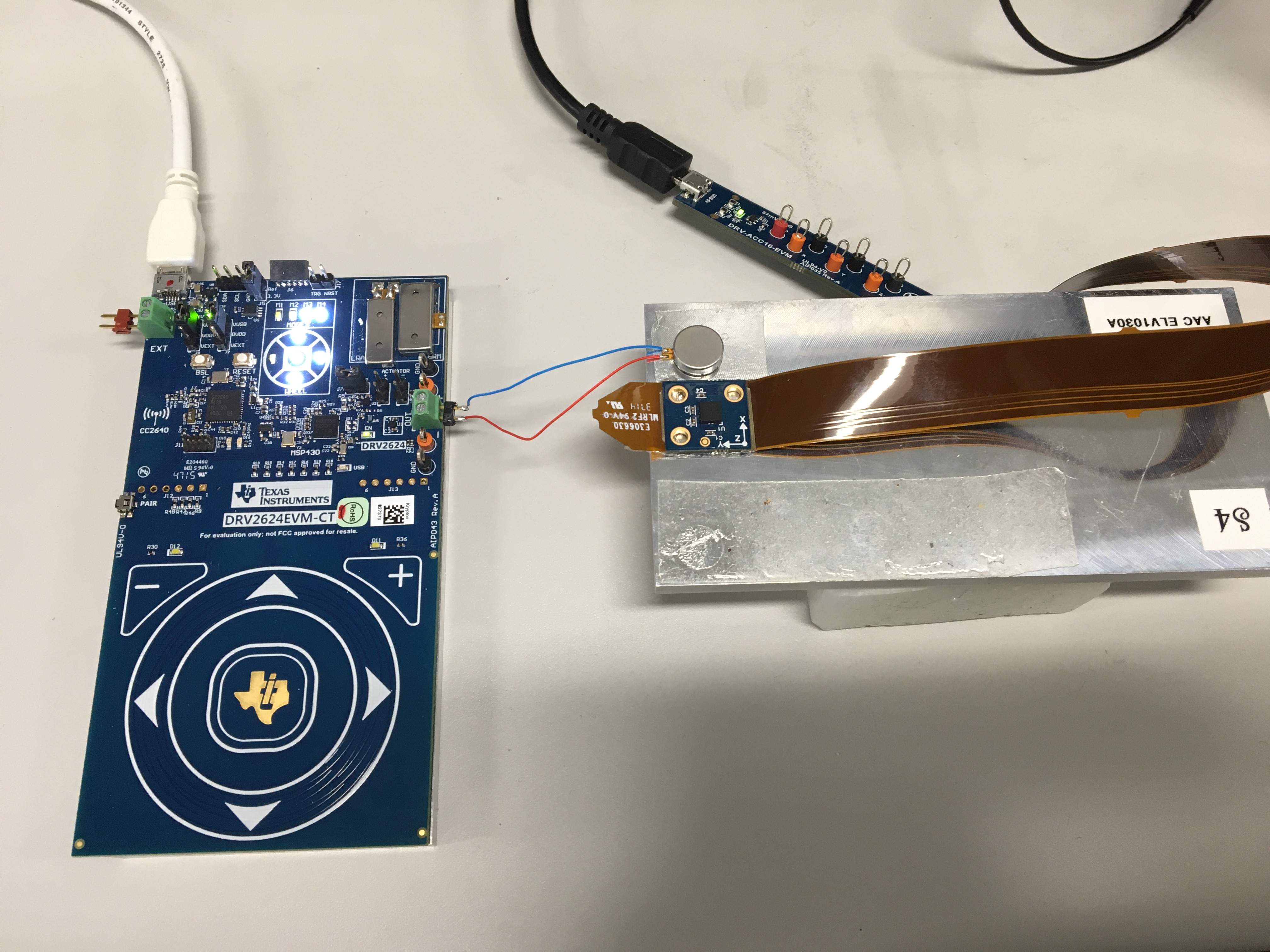
- Need some sort of representative mass to stick your LRA or ERM to
- The actuator being driven should be stuck in place, not able to rattle around at all
- Each LRA being tested has to be on a different representative mass otherwise they would dampen each other’s vibrations
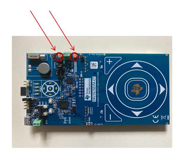
- The pins to record from the DRV2624/25 EVM are these
- To record the acceleration waveforms like in datasheet you need DRV-ACC16-EVM
- DRV-ACC-16 has sensor to stick to mass to record acceleration waveform of vibration
- There are three different acceleration pins to measure from on the DRV-ACC16 tool, should use Z axis pin if sticking onto mass like in picture at bottom unless you are using LRA oriented in Y or X axis
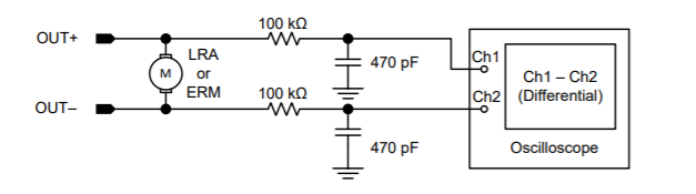
- If not using EVM need to recreate proper output filter here
- Use larger time division on oscilloscope to get waveform capture and then zoom in to avoid detecting too much of the remaining PWM switching frequency noise
- Should have some sort of isolating material between mass and rest of environment
- If you use EVM it has already attach representative mass
An example set-up of how an LRA should be recorded from using the DRV-ACC16 Accelerometer tool