This thread has been locked.

If you have a related question, please click the "Ask a related question" button in the top right corner. The newly created question will be automatically linked to this question.

DRV8302: Back EMF voltage during motor regeneration

Part Number: DRV8302

Hi,

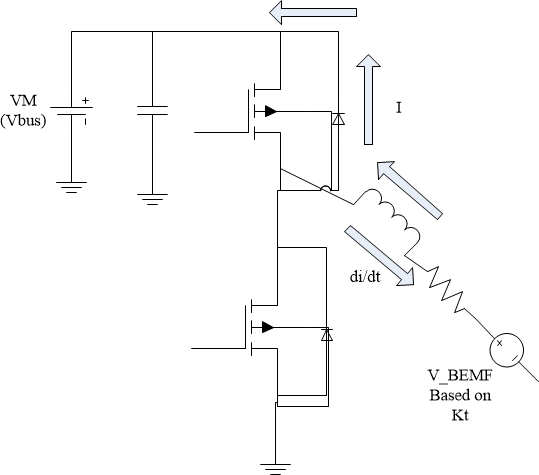
I'm trying to understand how the back EMF voltage of a motor can be higher than the bus during regeneration.  

During normal motor operation with speed omega, the back EMF voltage is lower than the bus voltage.  However, when the motor becomes a generator during regen braking, the bus voltage increases (assuming small bulk cap), which implies that the motor's back EMF voltage is higher than the bus.  Does this imply that the rotational speed of motor is faster during regeneration/braking than during normal motor operation?

I did some research but it's not very clear from what I found:

circuitglobe.com/regenerative-braking.html

Please explain

Thanks

-Kelvin

  • Hello Kelvin,

    Short Answer:

    Remember the inductive element (i.e. stator coil) of the motor stores energy. When we stop driving the motor, the magnetic field within the inductor collapses which means another BEMF is generated according to Lenz law. This is in addition of the BEMF generated by the motor BEMF constant. So both add together to be higher than the supply.

    Longer Answer:

    The below figure represents 1 phase of a brushless DC 3 phase motor.  

    This represents the moment the all FETs are turned off. Just before this moment, current was flowing through the inductor (inherent to the motor model). Normally, the current would have went into the low side FET. Since that FET is turned off, it is no longer a low impedance node and the current is looking for somewhere to flow and the magnetic core collapses. This means the di/dt (change in current) is in the opposite direction of current flow (see the arrow of di/dt in the figure).

    According to Lenz law, we will generate a back EMF (BEMF) in the opposite polarity of the di/dt. So we will get a positive voltage.

    Meanwhile, the rotor is still in motion. Inertia shows that the rotor will keep spinning. As the rotor, which is a magnetic element, continues to spin, it will continue to induce a voltage on the inductors (or stator coils). According to the motor BEMF constant, the speed (or frequency of the motor passing by the coils), will be proportional to the amplitude of the BEMF generated. It will not speed up, but slow down because of friction, etc.

    Finally, the we add the BEMF from the collapsing current with the BEMF induced by the spinning rotor, which generates a voltage higher than the bus voltage. For a very fast speed command (closer 100% of the bus voltage), the BEMF will be a little less than the bus voltage. This means it will not take a substantial amount of voltage to be higher than the supply voltage.

    With the voltage greater than the bus voltage, the current flows through the body diode of the FETs (so there is some loss through the body diodes), and the additional current will pump up the voltage if the bus cap cannot store that current flowing into the bus. 

    Best,

    -Cole

  • Thank you for the detailed answer Cole!