This thread has been locked.

If you have a related question, please click the "Ask a related question" button in the top right corner. The newly created question will be automatically linked to this question.

DRV2700: Booster working, Op Amp not.

Part Number: DRV2700

Hello.

I am using the DRV27001 in a design to drive a Piezo using a uC PWM output (via anti alias) to apply a sinus wave.

I am sure the design works. However, recently all hand soldered (hot air) implementations of the circuit do not work. The solder joint seems fine. The booster seems to work (110V can be measured on the boost capacitor) but no signals are amplified. Also, the boost capacitor is buzzing, though I wouldn't mind that.

I tried keeping the soldering temperature as low as possible. But is it a heat issue?

Am I simply bad at SMD soldering?

Is it a known thing?

The layout is correct but not optimized - could there be an issue there?

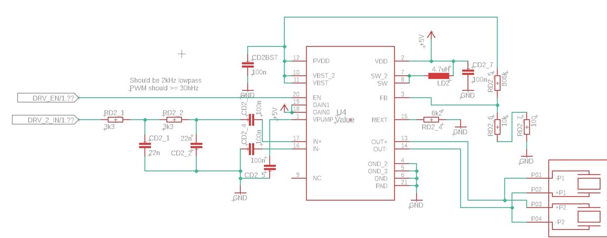
Here the circuit in question:

I managed to get it to work 3 out of 15 times (with different DRV2700 chips). All 4 DRV2700EVM boards I have work excellent.

Hope you can help,

best regards,

David

  • Hi, David,

    I think the best thing to ensure that the device amplifier is working properly is to verify the voltage levels at some points of the DRV2700.

    Could you see the voltage level at the pins below?

    - PVDD
    - EN
    - IN+ and IN- (no input signal)
    - OUT+ and OUT-

    In case of IN+ and IN- pins, you should see a level around VDD/2 on each pin when no input signal is used.

    Could you compare the voltage levels with the boards that work properly?

    On the DRV2700EVM, have you tested with the same components you are using in your design?

    Please let me know if you have any other observation.

    Thank you.

    Best regards,
    Luis Fernando Rodríguez S.

  • Thank you for the fast reply.

    I did check the signal path with an oscilloscope before without a result.

    EN: 5V, always.

    PVDD: 110V, always.

    In+ and IN-: 2.5V, always.

    Out+ and Out-

    50V when its working,

    about 3V when not.

    This is the issue as far as I can tell: no output independent of the input (even with a signal generator signal directly on IN+).

    In+ will have the AC input signal with a 2.5V offset when a signal is connected.

    One time it started kind of working when I bridged the IN- coupling capacitor - but only at on time, not reproducible.

    I did not test with the same components on the DRV2700EVM since it came populated. I just modified the anti alias filter.

    Best regards,

    David

  • Hi, David,

    Have you tried with different FB resistors values?

    Based on the recommended conditions of the datasheet, the minimum Vbst voltage should be 15V. But the values you are using result in ~10.8V.

    Could you tell me what is the expected Vbst level you would like to reach so I can suggest resistors values?

    Thank you.

    Best regards,
    Luis Fernando Rodríguez S.

  • Hello.

    Thank you for your answer. The values I chose should lead, according to the datasheet to a boost voltage of:

    Vbst = 1.3V*(1+806kOhm/10.1kOhm) = 105V which is close to what I measure. That is why I stated that the boosting works.

    I tried changing it to 1.3V*(1+806kOhm/11kOhm) = 96.6V and the Vbst changed accordingly in the circuit.

    Unfortunately, the Op Amp still does not work.

    Best regards,

    David

  • Hi, David,

    Are you testing your application with a connected load? Do you have the details about your load? Could you measure the output without load?

    Also, is the DRV2700 getting hot during your tests?

    Best regards,
    Luis Fernando Rodríguez S.

  • Hello.

    I measured and tested with and without my load. I can not give details, but it is a small piezo actuator which works well with the circuit when the circuit works.

    The output voltage with and without load do not differ at all.

    The DRV2700 does not get warm.

    It really looks like the Op Amp or the Op Amp output stage is simply not working. It is exactly the same behavior in all failed circuits. Is that a known issue e.g. due to overheating the chip during soldering?

    Best regards,

    David

  • Hi, David,

    We haven't seen cases of overheating due to the soldering on this device. But based on the behavior of the device, as you correctly mentioned, it seems that it was damaged in some part of the process. I would expect to see a damage on the boost converter instead of the amplifier, since it is the most sensitive part.

    Have you considered the recommended soldering profiles below?

    https://www.ti.com/lit/an/snoa292j/snoa292j.pdf

    Best regards,

    Luis Fernando Rodríguez S.

  • Hello.

    I see.

    Unfortunately I do not have quick access to a soldering oven for my prototype.

    I asked a colleague to solder it for me and will see how that turns out - though he will also have to rely on hand soldering.

    Best regards,

    David

  • Hello, David,

    Thank you for you response. Please let me know when you have any feedback from your colleague about the soldering process and temperatures he is using. This could give us a better approach to this issue.

    Thank you.

    Best regards,
    Luis Fernando Rodríguez S.

  • Hello, David,

    I will close this E2E thread for now. However, feel free to post your observations and comments on this or on a new thread.

    Thank you.

    Best regards,
    Luis Fernando Rodríguez S.

  • Hello.

    Thank you for your support.

    Soldering was not an issue. using lead based solder paste and high enough temperatures with hot air led to good solder joints.

    It turned out that the issue was the layout, where the high voltage capacitor was not close enough to the DRV2700, which is actually described int he datasheet.

    At least, with a slight redesign, the circuit worked immediately.

    Best regards,

    David