This thread has been locked.

If you have a related question, please click the "Ask a related question" button in the top right corner. The newly created question will be automatically linked to this question.

DRV8323R: DRV8323RHRGZR nFault loop

Part Number: DRV8323R
Other Parts Discussed in Thread: DRV8323

Hi,


we have designed a motor controller based on the eval. board BOOSTXL-DRV8323RS(DRV8323RHRGZR)

Our board never releases nFault.

We have compared all the readings of our board to the eval. board and they are all similar.

Voltage 12V and 18mA

Have tried with 24V with the same result. 


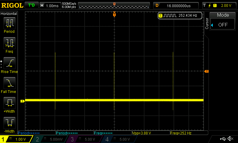
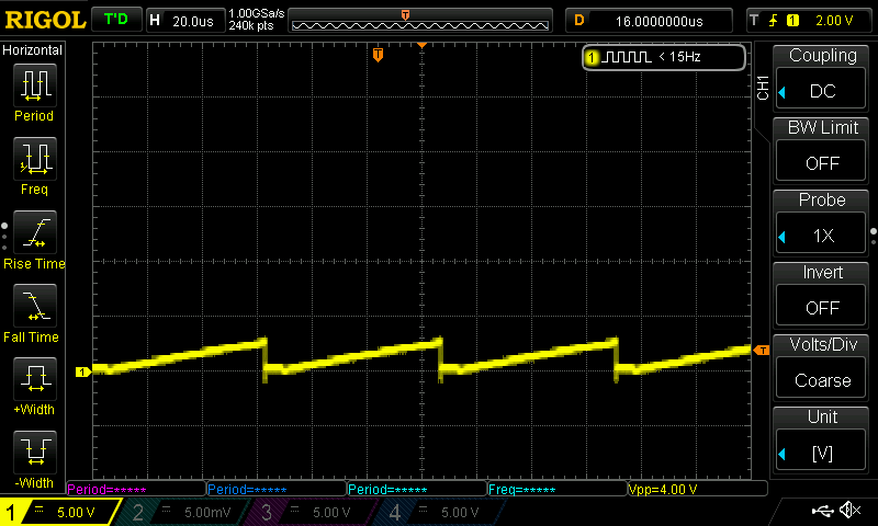
nFault pin. It resets every 4ms when INHA, INHB, INHC is set to low by the MCU.

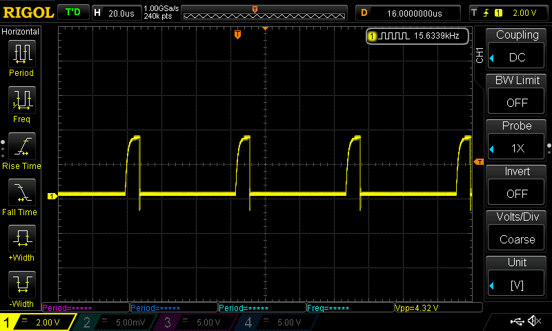
Nfault with 15kHz PWM signal

MOT_A with PWM signal:

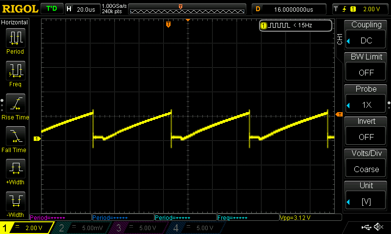
MOT_B with PWM signal

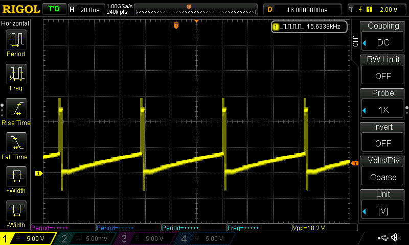
MOT_C with PWM signal

6170.sch.pdf

  • Hello Martin,

    Thanks for posting on the Motor Drive forums! Let me give you a full answer to your question on Monday. I'll need to do the schematic review, and look at the waveforms and see what next step we can do.

    For now, its clear the device is determining that something is wrong. The DRV8323 has a number of faults that we'll have to review. The periodic behavior can lead to a clue, the timing seems to line up with the activity on the motor phases so it might be related to driving the motor, such as gate drive fault, VDS over currents, etc (as opposed to a over temp fault or UVLO not related to a rail that drives the motor).

    If you have some time, take a look at the gate drive related faults and see if the waveforms fit the criteria outlined in the datasheet. If some of the faults don't make sense we have a back up plan; we might need to do some continuity checks to make sure there's no problems with the assembly of the layout.

    Best,

    -Cole

  • Thanks Cole,


    I've read through my post and some information is not clear. 

    Currently three is no motor connected. 

    Therefore the current draw is just from the circuit.

    When the eval. board is hooked up with no motor attached  the output is generating correcly, that’s why we have left motor disconnected.

    Have tried as best I can to compare the two boards and can't se any differences.

    Where should I check for continuity?

    Martin


  • Hello Martin,

    Continuity:

    Go ahead and check between all of the gate driver pins GHx and VDRAIN, GHx and SHx, GLx and SPx, SPx and SHx, etc. We're look for very low impedances (ohms) between them to see if something got shorted and damaged. If you can still plug in the motor and spin it, then it will show that this is not related to damage (might risk the damaging the rest of the components on board if the board is already somewhat damaged, you can always spin at slow speed and low currents so to minimize that risk)

    Waveforms:

    Can you confirm that the motor phase waveforms are a result of trying to commutate the motor phases and FETs with the default sensorless code? Or what was actually done?

    I'm surprised to see all of the motor phase voltages ramping linearly and together, but I'm not surprised to see that nFAULT is triggered after the first PWM is exposed to MOT_B. This leads us to believe that the DRV8323 is detecting a fault right when driving the motor and something goes wrong.

    Following up:

    Nothing seems to bad for the schematic.

    I discussed with the team today and there's some debate about the which fault could be culprit. It seems like the best course is for me to try and replicate this on the EVM. Unfortunately, it will take a little while so expect an answer, at latest on Thursday CDT.

    Best,

    -Cole

  • Hi Cole, thanks for your reply.

    Continuity:

    GHx and VDRAIN = 0.36M

    GHx and SHx  = 0.41M

    GLx and SPx = 52K

    SPx and SHx = 42K

    The motor has not moved at all. For the last week we have tried to compare it with the eval board to find what the error might be.

    Waveforms:

    I have tried the same code as we have used with the eval. board.

    The motor worked fine there.

    Tried connecting VDS to 3.3 to disable over current protection, nFault pulsing

    Removed the MCU from the board and connected Enable pin to 3.3V and the nFault keep pulsing every 4ms.

    Removed mosfets and the same pulsing.

    Will order new components and just add bare minimum to the PCB to see if it possible to get the IC to work. 

    Regards,

    Martin 


  • Hi Cole, 

    I made a board with the bare minimum and got it working.

    No issues with the board now and all components attached

    Think the problem might have been the HASL surface.

    Regards, 

    Martin