This thread has been locked.

If you have a related question, please click the "Ask a related question" button in the top right corner. The newly created question will be automatically linked to this question.

DRV8301: DRV8301 Buck Converter Output oscillation

Part Number: DRV8301

Hi,

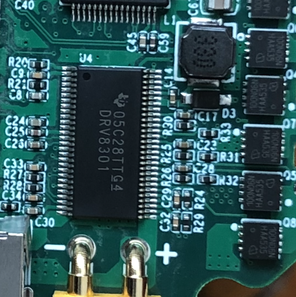
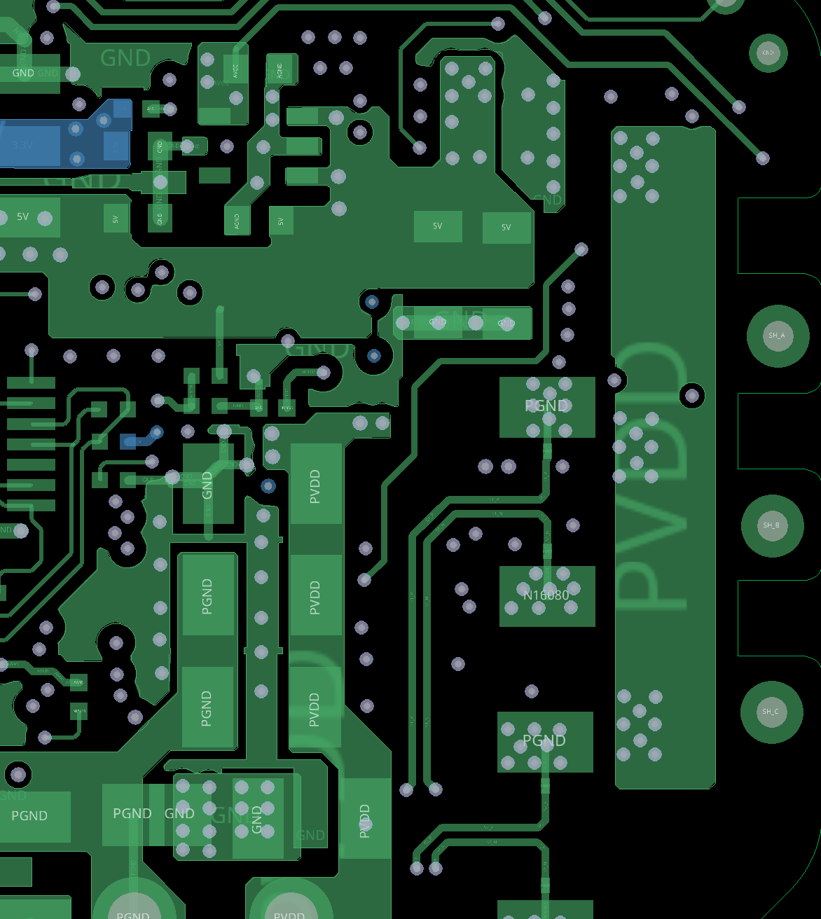
I designed a three phase motor controller using DRV8301, and found that the buck converter output have a very large oscillation. I also found no oscillation at light load. The output waveform, schematic and PCB layout are below. The PCB is six layer. The input Bus voltage is 24V.

  • I just solved this by replacing the multilayer ceramic output capacitor to the tantalum capacitor. The capacitance are the same (100uF). But I don't know why?


  • Hello haotian cui96,

    Thank you for posting on the motor drivers forum page! Thanks for providing schematics, layout, waveforms etc. It helps us answer questions more quickly.

    The buck regulators, and any device that deals with feedback from the output signal (such as an op amp) will have the deal with the concept of stability.  Sometimes, errors, parasitic, or bad component selection can result in the feedback to amplify unwanted noise or frequencies of internal signals. Stability is "likeliness of a system to react to a finite input with a finite output". The opposite is instability when you can put in a finite input and get an infinite output.

    So a perfectly stable buck, we would expect the see a perfectly clean square wave of the buck chopping the voltage down the desired one. An an unstable one is where the square wave would be applied but some other signal output is unexpected and periodic that will go on forever. The waveform with the oscillation seems to be unstable as the buck switches, a decaying sinusoid is introduce and continues to "ring" (or oscillate) long after the switching was stopped.

    Using applicable op amp knowledge about feedback, we know that adding different impendences into the feedback network (and at the output!) will cause the signal to amplify or attenuate at different frequencies. The LC output filter (or any time LC is introduced with switching nodes, such as bad layout with skinny and long traces) have a properties to resonate and amplify higher frequency signal that get fed back into the feedback path and cause this ringing (for the reasons above). 

    The reason why LC resonation occurs, is because inductors and caps are not perfectly ideal. The different types have different properties. One of them, is Equivalent Series Resistance (ESR). They are much higher in tantalum caps and much lower in ceramic caps. The increase ESR is like adding another resistor in the feedback path (which helps with the amplification of unstable signals). So, some designers will put a tantalum and ceramic cap in parallel (parallel resisitance, the smaller resistance is the dominate path) so they get the benefits of both passive components: Ceramic with ESR, and Tantalum for higher rated voltage and values. 

    Feel free to read more about "Output Noise Filtering for DC/DC Power Modules" app note where it goes over these concepts, and more.

     https://www.ti.com/lit/an/snva871/snva871.pdf 

  • Hi Cole Macias,

    Thanks for your reply !!! This really helps me a lot.