This thread has been locked.

If you have a related question, please click the "Ask a related question" button in the top right corner. The newly created question will be automatically linked to this question.

DRV8711: DEV8711EVM

Part Number: DRV8711

Hello.

I'm currently performing a series of testing related to driving a step motor using DRV8711EVM.
While conducting the test, unusual waveform at the gate signals;this is solely based on my personal observation, have been found.
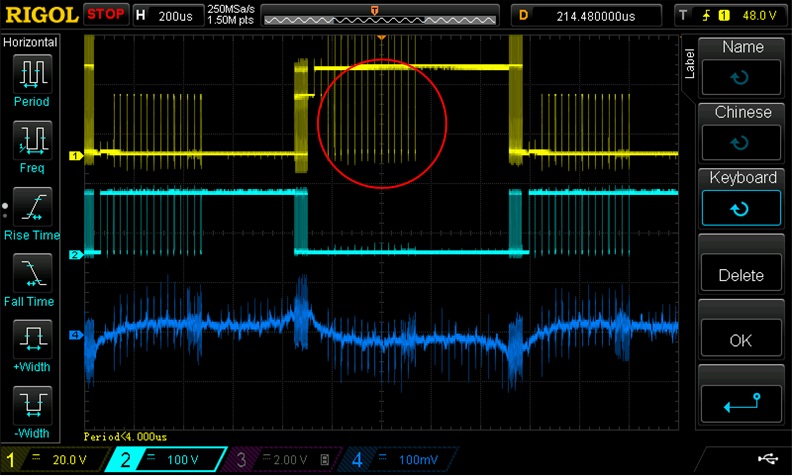
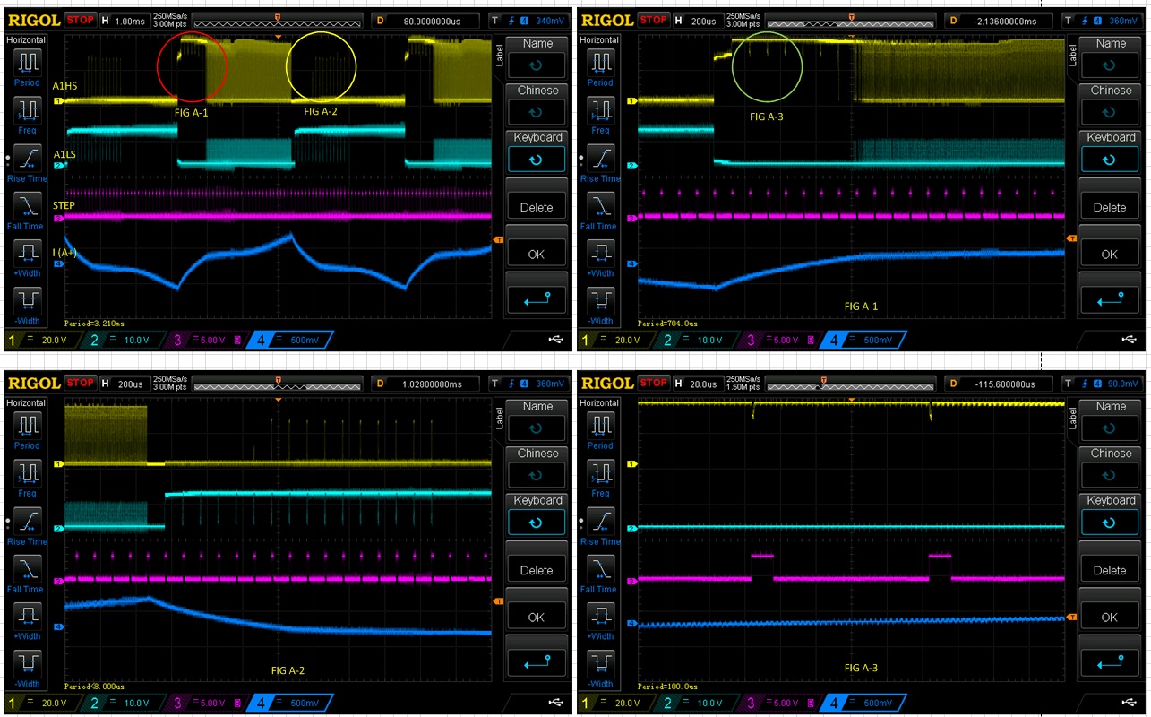
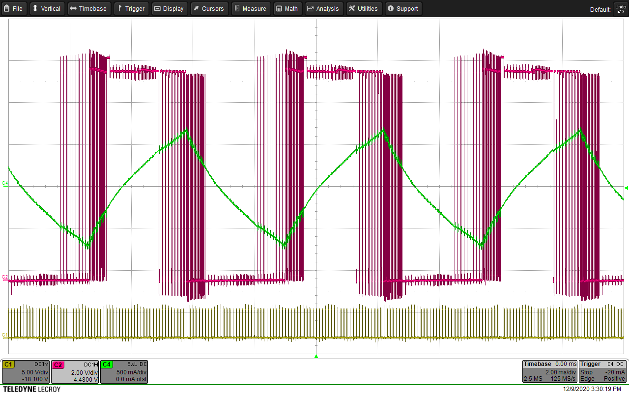
The unusual waveform I found during the test are shown in the picture below.

CH1 : A1HS
CH2 : A1LS
CH3 : NC
CH4 : Current Probe (A+)

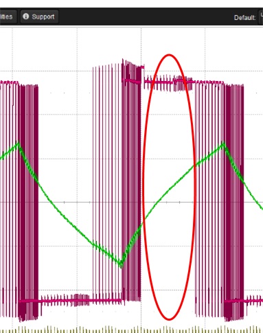
I expected A1HS to be remained "Turned ON" at all times as the section indicated between two red lines is considered as "I_trip > I".
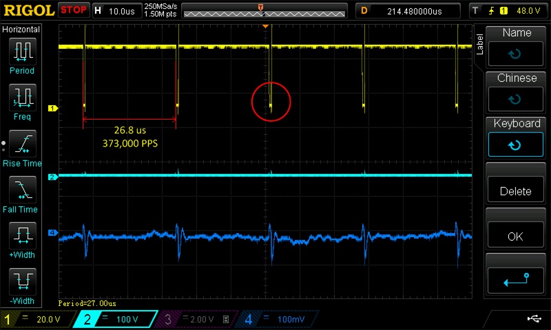
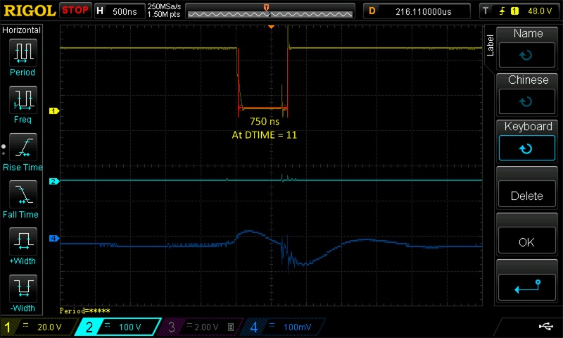
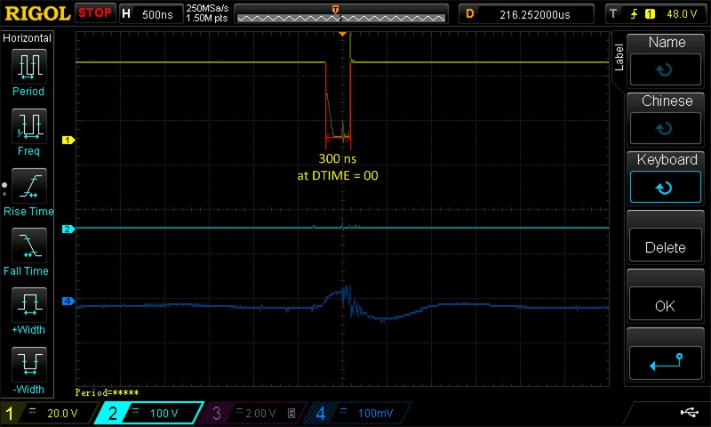
However, as shown in the circle indicated in red, it was found A1HS has been turned off for a moment.
(The duty and period of this signal seems to be T_off and PPS, respectively.)

Please provide me with the detail explanation regarding the matter mentioned above.

Thank you.

Best Regards.

  • Hi JeongHoon Kim,

    Thank you for posting to the motor drives forum.

    Let us take some time to research your question and provide a detailed answer by 11/25 or earlier. 

  • Hi JeongHoon Kim,

    During the current regulation, the device will either try to limit the current by adjusting the PWM duty cycle or fully turn on the FETs to allow the current to reach the Itrip point. Section 7.3.5 in the datasheet explains this well.

    In your case, it looks like the device tries to limit the current for some time but then fully enables the HS FET to allow the current to rise until it reaches ITRIP. Usually a combination of low VM and high speed (or high back-emf) can cause the current through the winding to take longer to reach Itrip.

    I hope this answers your question.

  • Thank you for your answer.
    And I have additional questions.

    I wonder what happens to A1HS if I<I_trip until the current microstep is completed.
    When a new microstep is started, does the A1HS always turn off and turn on again?
    If so, why the OFF waveform is not seen in the yellow circle?

    And, there was a mistake in previous inquiry. (The A1HS off time is same as T_dead, not T_off.)

    Thank you.

    Best Regard

  • Mr. Kim,

    It is Thanksgiving holiday in US, so Pablo is out of the office.  

    I would like to understand more about your measurements.  Can you zoom in more on the plot above that shows dips in the A1HS?  I would like to understand this better.

    Also, can you add the STEP signal to this scope capture so we can see when the device is commanded to the next micro-step?

  • Hi. Ryan.

    These pictures are zoomed scope capture of A1HS.
    (I'm sorry I forgot to add STEP signal. If you really need to see that signal at the same time, I'll capture that again.)

    When I captured scope screen, I set STEP frequency to 37,000 Hz.
    The width between drops was 26.8us. (1000000us / 37000Hz = 27 us)

    When DTIME is set to 11, you can see that the width of drop is 750ns.

    And, when I changed DTIME to 00, the width of drop also changed to 300 ns.

    Thank you and have a nice weekend.

    Best Regards,

  • Thank you for the additional plots.  

    Few more questions:

    1)  What level of micro-stepping is being used?  

    2)  What do you have your full scale current set to?

    3)  Is the motor moving as expected on each step?  I am asking this as the current waveform does not look normal.

    If you could add the step pulse to the plot, it would be helpful.  

  • Thank you for your reply.

    1) What level of micro-stepping is being used? 

    => 1/16 step

    2) What do you have your full scale current set to?

    => 1.5 A

    3) Is the motor moving as expected on each step? I am asking this as the current waveform does not look normal.
    =>
    Yes, motor moves well without out of step.
    The command step speed is 37 kpps. (I wrote 373,000pps in previous posting, it was typo.)
    Considering the 1/6 micro step condition, the speed is quite high. and so, current waveform is bad because of back EMF.
    Nevertheless, the motor rotates well.
    However, the maximum torque is smaller than expected, so we are looking for the cause.
    I suspect that it is one of the causes.

    Thank you.

    Best Regards,

  • Hi JeongHoon Kim,

    Thank you for providing the information. Just to confirm, is the micro-step 1/16 or 1/6? you mentioned both numbers in your previous reply.

    Can you also provide another scope shot showing the STEP signal like Ryan suggested? Right now it is very difficult to determine when the driver is stepping due to the abnormal current waveform shape. Knowing this information will help us understand the waveforms you attached and to know whether this is expected behavior from the driver.

  • Hi. Pablo.

    The micro-step is 1/16.

    I'll add step pulse signal and post it again.

    Is there any other signals that you want to see?

    Thank you.

    Best Regards,

  • Hi JeongHoon,

    Yes. aside from the STEP signal, can you provide a scope shot showing B1HS, B1LS, STEP, and BOUT1 current. Make sure that the current probe orientation points in the same direction as the current probe connected to AOUT1 (from the previous measurement). This is to ensure consistency between both scope shots.

  • Hi. Pablo.

    I captured some signals what you need using DRV8711EVM.

    Test Condition : 

    Coil A Signals with STEP.

    Coil B Signals with STEP

    Feel free to request any signal you need to check.

    Thank you for your help.

    Best Regards,

  • Hi JeongHoon,

    Thank you for providing the detailed waveforms. Let me take some time to look at these waveforms and determine if this is expected behavior from the driver. Expect a reply from by by 12/04 US time or earlier. 

  • Hi JeongHoon,

    I am having a difficult time determinize if these waveforms are expected behavior of the driver. In earlier waveforms that you sent, the location where the PWMing (or current regulation) occurs is different from this new waveforms. Maybe you measure the current of different terminals in both sets of waveforms?

    Since you provided a screenshot of the GUI set-up, I will recreate the set-up using the DRV8711EVM and compare my results to yours. I will reply back on 12/07 or earlier with my results and hopefully the answer to your question.

    I appreciate your patience with me so far.

  • Hi JeongHoon,

    I apologize for the delay response.

    Please give me an extra day to understand the waveforms. 

    Thank you for your patience.

  • Hi JeongHoon,

    Thank you again for your patience with us.

    I used a DRV8711EVM in our lab with a stepper motor with the same GUI configurations as yours. Below are two waveforms I capture. The top waveforms is with the speed of the motor set to 1000pps and the bottom waveforms is with the motor speed set to 10000pps. 

    The reason for the abnormal current waveform with the higher speed motor is due to the higher BEMF. The BEMF will always oppose the current change through the motor inductance. The higher the speed, the stronger the BEMF which will cause the driver to provide the full VM voltage across the inductor to try and increase the current to the ITRIP value for each STEP. 

    I hope this helps you understand how current regulation works in our drivers. 

    I suggest reading this app-note to learn more about how current is regulated in stepper motors

    Speed: 10000pps; CH1=STEP, CH2=A+ voltage, CH3=A+ Current.

  • Hi, Pablo.

    It's me again.

    Thank you for your kind reply.

    I can't check your replay for some reasons. I'm sorry about that.

    I understand that that the current waveform was affected by BEMF.

    And, I keep wondering about that why A1HS turn off for a moment in my experiment.

    In your waveform (in red circle), I think that A1HS is ON(without OFF) since I is lower than I_trip.

    But, in my board, I saw A1HS has been turned off for a moment even when I<I_trip.

    The period of off signal is same with step period and the width of off signal is concerned with t_dead.

    So, I wonder what happens to A1HS if I<I_trip until the microstep is completed.

    When a new microstep is started, does the A1HS always turn off for a moment and turn on again?

    If so, why the OFF waveform is not seen in your capture ? (the area where I draw red circle)

    Thank you.

    Best Regards,

  • Hi JeongHoon,

    The A1HS should not "turn off" at the beginning of every step unless the current overshoots above I_trip at the beginning of each step. If the current does overshoot momentarily at the beginning of each step, then the driver will regulate the current by disabling the outputs for T_OFF.

    Have you tried driving the motor at a slower speed such that the current waveform is closer to a sinusoidal waveform similar to the waveform I attached in my previous reply. Are the pulses at during each STEP signal visible? I suspect the pulses to go away at a slower speed. In your waveforms I can see that there are spikes in the current waveform which seems to line up with the beginning of each step.