


Understanding the parameters of a motor is very important in selecting a motor driver as the rating of the FETs and control method of the Motor driver depends on motor parameters and construction. A motor has electrical and mechanical parameters listed in the datasheet as it is an electro-mechanical machine that converts electrical energy to mechanical energy.
Electrical circuit model of a Brushless DC (BLDC) Motor showing electrical and mechanical parameters is shown in Figure 1.
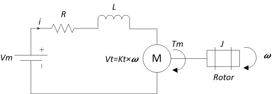
Figure 1. Electrical Circuit Model of BLDC Motor
The following table lists and explains the electrical and mechanical parameters of a BLDC motor.
|
Electrical Parameter |
Typical Symbol |
Unit |
Definition |
|
Rated voltage |
Vm |
Volts |
Rated voltage that is applied to the motor phases. |
|
Rated current |
i |
Ampere |
Current drawn by the motor when the motor is loaded at rated torque. |
|
No load current |
inl |
Ampere |
Current drawn by the motor when there is no load on the motor shaft. |
|
Peak current/stall current |
ipk |
Ampere |
Current drawn by the motor when the motor shaft gets locked. |
|
Back EMF constant |
Kt |
v/Hz or v/rpm or v/rad/sec |
Induced voltage Vt on stator windings at 1 Hz or 1 rpm or 1 rad/sec. |
|
Stator/Winding resistance |
R |
Ω |
Resistance across two phases of the motor. |
|
Stator/Winding inductance |
L |
H |
Inductance across two phases of the motor. |
|
Mechanical Parameter |
Typical Symbol |
Unit |
Definition |
|
Rated Speed |
Hz or rpm or rad/sec |
Rated speed of the motor. |
|
|
Rated Torque |
Tm |
Nm |
Torque generated by the motor at rated speed. |
|
Stall Torque |
Ts |
Nm |
Maximum load torque at which the rotor gets locked. |
|
Rotor inertia |
J |
Oz-in-s2/N-m-s2 |
Rotor moment of inertia. This is useful to determine the acceleration and deceleration rates, the dynamic response of the system and to calculate the mechanical time constant of the rotor. |
Table 1. Electrical and Mechanical parameters of a BLDC motor.
How to select a BLDC motor driver based on the information available in Motor Datasheet?
Determining voltage and current rating of the integrated FETs based on the motor voltage and current rating is the first step in selecting a Motor driver.
Below are the parameters in the motor datasheet that should be considered when selecting a Motor driver with integrated FET architecture.
- Rated Voltage Vm
- Peak current ipk
Power supply voltage Vs (Abs max) and peak output current is of the integrated FET device (listed in table 2) should be compared with rated voltage Vm and peak current ipk of the motor. Vs and is should be slightly greater than Vm and ipk.
Below are the parameters in the motor datasheet that should be considered while selecting a Motor driver with integrated control architecture.
- Rated Voltage Vm
- Peak current ipk
- Rated current i
- Back EMF Constant Kt
- Stator resistance R
- Stator inductance L
Similar to integrated FET devices, Vs and is of integrated control devices should be slightly higher than Vm and ipk. Motor parameters such as R, L and Kt are used in the motor control algorithm of integrated control devices. R, L and Kt in the motor datasheet should be within the applicable range of R, L and Kt (listed in table 2) that the integrated control device can support.
|
Device |
Architecture |
Power Supply voltage Vs |
Peak Current is |
Motor phase-phase resistance |
Motor phase-phase inductance (mH) |
BEMF Constant Kt (mV/Hz) |
|||
|
Abs Max |
Abs Max |
Min |
Max |
Min |
Max |
Min |
Max |
||
|
DRV8313 |
Integrated FET |
65 |
3 |
N/A |
N/A |
N/A |
|||
|
DRV8312 |
Integrated FET |
70 |
6.5 |
||||||
|
DRV8332 |
Integrated FET |
70 |
13 |
||||||
|
DRV10964 |
Integrated Control |
5.5 |
0.875 |
5 |
20 |
0.05 |
1 |
1 |
100 |
|
DRV10970 |
Integrated Control |
18 |
1.5 |
N/A |
N/A |
N/A |
N/A |
N/A |
N/A |
|
DRV10974 |
Integrated Control |
20 |
2.5 |
2 |
40 |
0.07 |
|
5 |
150 |
|
DRV10975 |
Integrated Control |
18 |
2 |
0.6 |
24 |
0.07 |
|
1 |
1800 |
|
DRV10983 |
Integrated Control |
28 |
3 |
0.6 |
38 |
0.07 |
|
1 |
1800 |
|
DRV10983-Q1 |
Integrated Control |
28 |
3 |
0.6 |
38 |
0.07 |
|
1 |
1800 |
|
DRV10987 |
Integrated Control |
28 |
3 |
0.6 |
38 |
0.07 |
|
1 |
1800 |
Table 2. Integrated FET and Integrated Control device parameters.
For more details, please refer to the Brushless-DC Motor Driver Considerations and Selection Guide.
