Other Parts Discussed in Thread: DRV8711,
I am using a 24VDC 200W motor with this driver chip in a full bridge configuration with 2 redundant MOSFETs to account for high temperature and current. I am seeing a fault where the fault pin is pulled low, but VCP, VM and AVDD are all measured as normal (within tolerance and typical of normal operation). Once the fault is present, it will keep happening consistently until I power cycle the VM power (24V power to both motor and logic power for the driver IC).
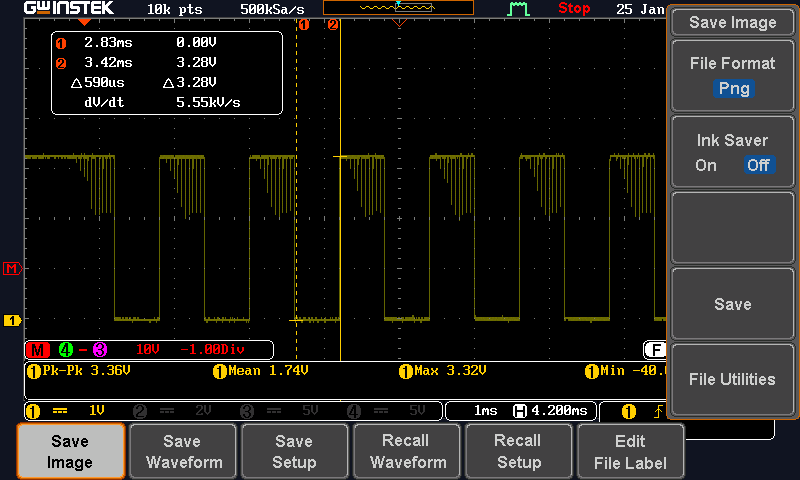
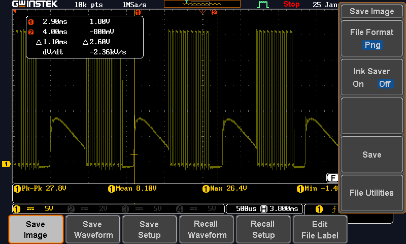
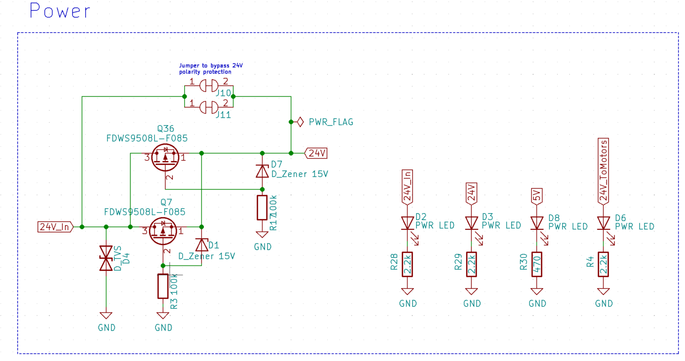
When the fault state is active, the fault line transitions low when sending higher speed PWM commands and the motor will not move, but sending slower PWM commands still moves the motor with no fault. Cutting power and reconnecting will always solve the issue and the motor will start responding 100% of the time for both high speed and low speed PWM commands after cycling. PWM frequency is 20kHz. The issue seems to happen maybe 1 out of 20 times on power up, and worried our end users will become upset when observing this fault state. I have attached the schematic below, and hopefully you can provide some feedback.
Please note, I found in the datasheet where it says there is no need for gate resistors with this IC and replaced the 2ohm resistors with 0 ohm jumpers. I have placed a 68kOhm resistor from IDRIVE to AVDD for fastest tdrive current (all other values do not work, as in the motor will not move at all at any speed, 100% of the time). I suspect the issue is large capacitance of the high power FETs affecting tdrive, but if anyone can spot other potential issues, please let me know.
MOSFETs being used: NVMTS0D4N04CLTXG