A related question is a question created from another question. When the related question is created, it will be automatically linked to the original question.
If you have a related question, please click the "Ask a related question" button in the top right corner. The newly created question will be automatically linked to this question.
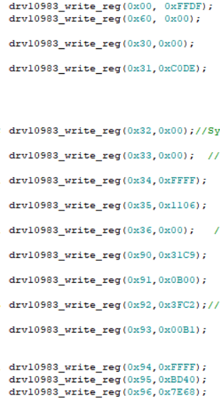
DRV10983 car level use problem: the parameters configured for non-car level are transplanted to the car level, the motor starts normally, but stops after several turns, and then stops again after rotation.This phenomenon should be which module, which register, which value has the problem?The configuration registers are as follows
Can you tell us which device you are working on? If it is DRV10983 then you are programming wrong set of registers. The registers that you shared are for DRV10983-Q1. Also, the motor's inductance is too low based on the recommended applications table (table 36) in the datasheet. There might be issues in spinning low inductance motors at higher speeds using DRV10983-Q1. If you are working on DRV10983-Q1 then can you read the fault register (address: 0x00) and tell us what fault is getting triggered? In case if you are using DRV10983, read register address 0x1E to know the fault.
1. How is the EEPROM of this chip configured?Can there be a more detailed explanation of the contents, such as the Shadow Register?
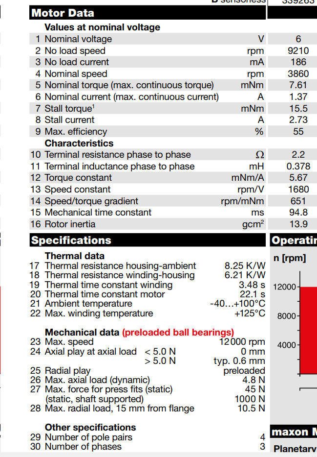
2. In the last reply, the car standard chip is not suitable for high speed and low inductance motor. What is the dividing line between low inductance and high inductance?
3,10983 chip can not configure EEPROM, 10983Q can also be enabled, can only enable the configuration of motor parameters in the parameter configuration register?
4. Attached is my configuration. Please help me to make reasonable configuration according to my motor and use
1. I'm still not sure if you are using DRV10983 or DRV10983-Q1. If you are using DRV10983, please refer to section 8.3.5 in the datasheet for instructions on how to program EEPROM. If you are using DRV10983-Q1, please refer to section 8.3.6 in the datasheet. I'm not sure what you mean by "Contents". If you are looking for register contents, please refer to register maps section in the datasheet.
2. Minimum recommended phase -phase inductance that DRV10983-Q1 and DRV10983 can support is 0.07 mH. There is a typo in the datasheet. Sorry about that. DRV10983-Q1 and DRV10983 should be able to spin your motor without any issues.
3. As mentioned in #1, please refer to section 8.3.5 in the datasheet for instructions on how to program EEPROM in DRV10983. In DRV10983-Q1, registers 0x90 to 0x96 are the registers that can be configured and saved in EEPROM memory.
4. Did you attach the register configuration (.csv) file? Sorry, I couldn't find it. Can you re-upload?
1. I2C did not communicate successfully, so the data read out is wrong.Has the official reference been made to the timing of I2C?2, how to analyze the transfer will stop the problem.3. Difference between car class and non-car class.The maximum value of I2C on page 30 of the manual is 511. The actual value read back is higher than that in the manual.
Please refer to section 8.5.1 in the datasheet for details on the I2C protocol for read and write operation. Did you follow all the steps mentioned in section 8.3.6 in the datasheet? Also, we recommend a pullup resistor of 4.7 kΩ to 3.3 V for I2C interface ports SCL and SDA.
511 is the maximum I2C speed code in decimal that can be programmed in the speed command register. This corresponds to 100% duty cycle. 511 is not the actual speed. At 511, the duty cycle is 100% and the motor is expected to spin at full speed.
First of all, the hardware circuitry is designed exactly according to the chip manual, no problem.Second, please give me some advice on the motor configuration we will be using.Finally, when the voltage does not exceed 22V, the 10983 can be configured directly into the 11000000 register EECTRL, so it is impractical to retain the EEPROM.Can 10983Q be set directly like this?If possible, please tell me which register of 10983Q has this function.
drv10983_write_reg(0x60, 0x8000);
drv10983_write_reg(0x31, 0x0000);
drv10983_write_reg(0x31, 0xC0DE);
drv10983_write_reg(0x32, 0x0001);
drv10983_write_reg(0x90, 0x31C9);
drv10983_write_reg(0x91, 0x0B00);
drv10983_write_reg(0x92, 0x3FC2);
drv10983_write_reg(0x93, 0x01B1);
drv10983_write_reg(0x94, 0xFFFF);
drv10983_write_reg(0x95, 0xBD40);
drv10983_write_reg(0x96, 0x7E68);
drv10983_write_reg(0x35, 0x0006);
drv10983_write_reg(0x35, 0x0002);
drv10983_write_reg(0x60, 0x0000);
These configurations are in accordance with the requirements of 8.3.6, but the effect is that the motor cannot start.The motor can be driven at 10983,so the values of resistance and BEMF are correct.Please suggest the correct modifications to the above configurations
1. Power up with any voltage within operating voltage range (6.2 V to 28 V) 2. (DRV10983Q only) Exit from sleep condition 3. Wait 10 ms 4. Write register 0x60 to set MTR_DIS = 1; this disables the motor driver. 5. Write register 0x31 with 0x0000 to clear the EEPROM access code 6. Write register 0x31 with 0xC0DE to enable access to EEPROM 7. Read register 0x32 for eeReadyStatus = 1 8. Case-A: Mass Write A. Write all individual shadow registers a. Write register 0x90 (CONFIG1) with CONFIG1 data b. ...
c. Write register 0x96 (CONFIG7) with CONFIG7 data
B. Write the following to register 0x35
a. ShadowRegEn = 0
b. eeRefresh = 0
c. eeWRnEn = 1
d. EEPROM Access Mode = 10
C. Wait for register 0x32 eeReadyStatus = 1 – EEPROM is now updated with the contents of the shadow registers.
In section step 7 you should be reading register 0x32 for eeReadyStatus = 1 but I see that you are writing to the same register. After step 8.B do you read 0x32 to check if eeReadyStatus = 1? Similarly, during mass read, after step 9.B, do you read 0x32 to check if eeReadyStatus = 1?
We made the change according to the order in the manual, but still couldn't achieve rotation.I hope you can directly provide a technician who can communicate with me directly through telephone and other ways to help us.
In the 10983 configuration, I was able to configure the data directly in the register by configuring the address 0x03.I would like the 10983Q to be able to configure data directly in registers as well, regardless of EEPROM programming.