This thread has been locked.

If you have a related question, please click the "Ask a related question" button in the top right corner. The newly created question will be automatically linked to this question.

DRV11873: Drv11873 internal 5V LDO has no voltage output

Part Number: DRV11873

Drv11873 can not work in the application. The output voltage of 5V LDO is 0V.

The following attempts have been made       

  1. Connect the external 5V voltage to the 5V output port of the IC, and the motor works normally; 

  2. Worried that the 5V current exceeds the load current by 20mA, the external 5V current is tested by an external instrument, and the measured value is 0ma (the current does not flow from external 5V);       

  3. Disconnect the external 5V input. The magic thing is that the internal 5V has output again and the motor works normally (so far, at least two machines without 5V output have appeared).

So the DRV11873 internal how to contorl the 5V LDO output ? We use 50% PWM input to control the DRV11873,and VCC is 12V.Power on sencuence is first PWM input,sencond 12V setup ,and the Interval 210ms .

Motor  parameter: Terminal Resistance:4.5Ω    Inductance:1.0mH   Kt:0.006Nm/A   12poles 3 phases, Brush less.

Please let me know if you need any other information ,Sincerely looking forward to your reply .

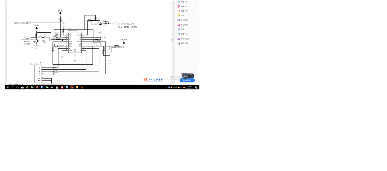
Follow is the SCH :

  • Hi Chris,

    Thanks for posting your question in MD forum. From your schematic I see that you are loading the internal 5V LDO to generate PWM signal. I think this PWM circuit is drawing more than 20 mA during the power up and this triggers UVLO fault on V5.When you connect external 5V, the device comes out of UVLO fault and spins the motor.  I'm guessing V5 is overloaded by the PWM circuit (may be inrush current) during the powerup and then the load current settles down to below 20 mA during normal operation. 

    Can you apply around 5.2V to the V5 pin using an external power supply and see how much current is drawn during the power up?

    Also, do you see this issue when there is no load on V5 pin? 

    Regards,

    Vishnu.

  • Hi Vishnu:

    I have tested the current of external 5.2V power supply and the sartup current is 30~40mA by Fluke(The accuracy of current probe is not enough ),after is about 3mArms.But,We have done the following applications(It has been in mass production for one year ) :Power supply is 6V,PWM pin external pullup 100K to 5V.There is no 5V LDO has no output phenomenon.

    About UVLO,UVLO fault  will be cleared when the power supply restarts?  This phenomenon will not disappear with the power on again .

    When use extarnal 5.2V supply ,all current will go to the external power supply? By the way ,when use external 5.2V power supply,the Motor start-up jitter will be greater than internal 5V. I'm afraid this will affect the start-up current of V5.

    If it is really like what you analyzed, how to solve the rush current at the moment of power on.  Also my my system needs PWM to control the speed .Is there a reference application circuit ?

    Best Regards!

    Chris.


  • Hi Vishnu:

    I  update the information, I just received a machine with this problem, but the phenomenon is different from the previous machine. Also there is no 5V output ,and connect the V5 to external 5V, the motor doesn't work.Restart the power,remove the external 5V,5V LDO has output,but motor doesn't work either.

    I check the volatge of U\V\W\COM.Vu=Vv=Vw=about 3V (just DC Voltage test by Oscilloscope),Vcom=0.2V DC. Normal Vu=Vv=Vw=Vcom=6Vrms,when power supply is 12V PWM input 50% .

    Hope to help analyze the problem 

    Best Regards!

    Chris.


  • Hi Chris,

    As expected, the PWM circuit is drawing above 20 mA and that's triggering UVLO fault on V5. UVLO fault gets cleared when the voltage rises above 4.3V (typical). At 5.2V (external power supply), load will be completely on the external power supply. To reduce inrush current,  you may try increasing the input impedance of the PWM circuit. Please refer to the DRV11873EVM design files for details on designing the PWM circuit. 

    Regards,

    Vishnu

  • If you do not see 5V on the V5 pin then the device is mostly damaged. 

  • Hi Vishnu:

    I check the DRV11873EVM SCH design. PWM input pin use 10K pull-up,Series resistance is 0R.My application use 10k Pull-up,series resistance is 10K. So i don't think there is a problem here.

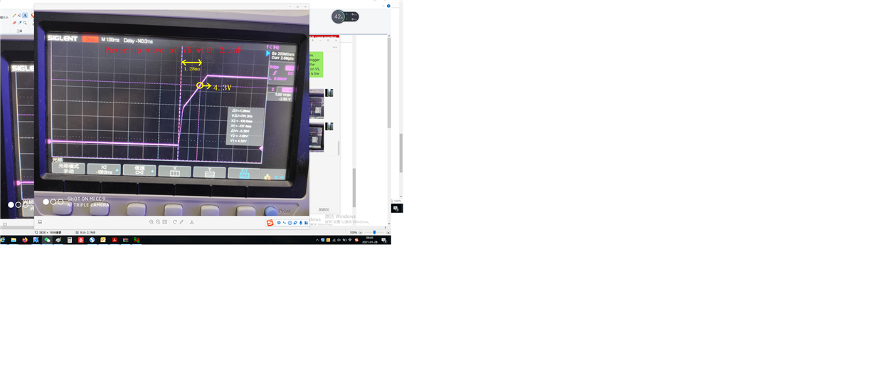
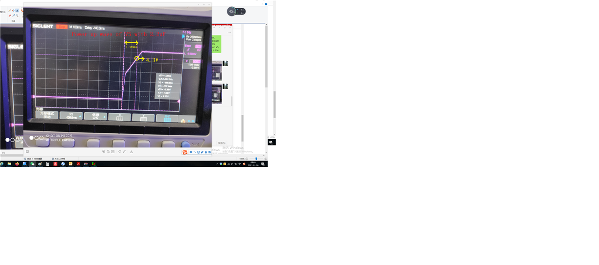
    Maybe the external capacitance of V5 is a problem.Demo design is 2.2uF ,my application is 10uF . A bigger capacitance produces a larger rush current.I test the power-up sencence of V5.If there is a UVLO fault on V5, the voltage of V5 must will be under 4.3V. Following is the 5V power-up wave of 2.2uf and 10uF.

    There is no collapse of the 5V waveform here(Motor successful starts) and when the voltage reached 4.3V the capacitance of 2.2uf needs 1.28ms, while that of 10uF needs 1.56ms .How long does it take from 5V power-up to UVLO detection ? By the way ,the logci of DRV11873 is also uses the V5 power supply ,if the V5 is not normally, logic circuit  will crash and  burn the MOS-FET?


    Best Regards!

    Chris.

  • Hi Chris,

    DRV11873EVM works fine so can you try replacing your PWM circuit with the PWM signal generation circuit in the EVM? Clearly, it is your PWM circuit that is overloading the V5 power supply. 

    Regards,

    Vishnu.