This thread has been locked.

If you have a related question, please click the "Ask a related question" button in the top right corner. The newly created question will be automatically linked to this question.

DRV8350S-EVM: something wrong with the VGLS

Part Number: DRV8350S-EVM
Other Parts Discussed in Thread: DRV8350, CSD88537ND

hello;

      these days I try to make some protection for drv8350.Our board use 3 drv8350 to drive 3 BLDC. We have produce 50 PCB .But we found a problen in one board.

When we power on ,all drv8350 occur fault UVLO. And the power is right 24V ,the vgls is right 16V ,and the vcp is rigth  35V. So we reset the fault .Every thing seems 

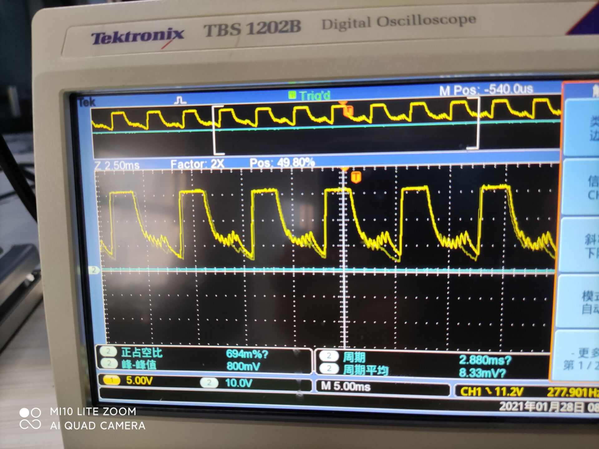
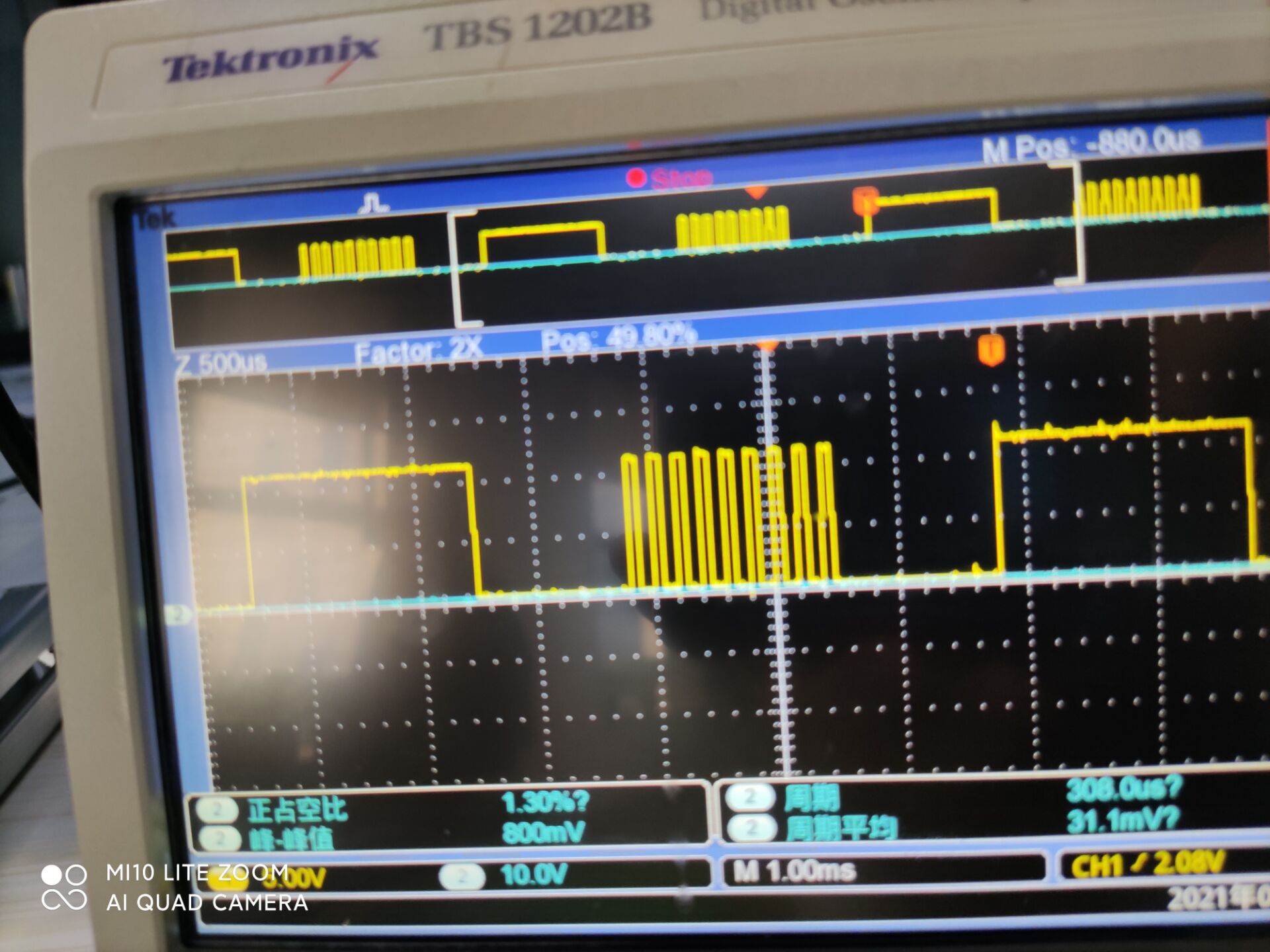
ok.So we let the motor run(but we don;t connet the bldc but connect the bldc is the same) .And we can see it occur fault again  GDUV).We found that the VGLS drop to 

0V.If we connect bldc, the bldc  run slowly anc can be easily stopped.Because the VGLS becomes a square wave oscillating from 0 to 10V.The resistance values of

VGLS and GLA SLA were normal in our test,about 1M ,270K.

   So what do you think make the vgls drop to 0V.  I am very confused.

thanks 

shengMotor.pdfzhong


  • Hello Shengzhong,

    Thanks for your question.

    I see that you are using the SPI device. What is the IDRIVE setting that you are using? We often see that if IDRIVE is set too high it can result in damage to the device. [FAQ] Selecting the Best IDRIVE setting and Why this is Essential.

    Check on the SLx and GLx pins during normal operation to see if you are exceeding the abs max ratings of these pins due to negative or positive voltage transients.

    Can you perform a part swap to ensure that the issue follows the device rather than the board? This can isolate where the issue is occurring.

    Thanks,

    Matt

  • hello Matt 

    thanks for your advice.

    I have performed apart swap to a good board before.The chip seems work well in another board.

    The slx glx signal ,u can see it in the picture.I also add the vgls. U can see the vgls and gla is wrong. It seems lose some duty cycle.The vgls should be  stable 

    11V but there is  aperopdoc oscillation .I have test the INLA from MUC. It‘s normal but the Drv8350 output wrong pwm. The Idrive is 2000mA and 1000mA.

    If go by u guess,the what did the high Idive destroy? Because we have proved the drv8350 is good,it is strange right?

    Looking forward to your reply

    best

    shengzhong

  • this is vgls .The next one is riigh glx and wrong glx

  • Hello Shengzhong,

    The device replaced on a different board recovers, which implies an issue on the board. That is strange.

    We do not recommend using the highest IDRIVE setting, since this has been shown to cause abnormal behavior or possibly damage. We generally recommend setting IDRIVE so that QGD / IDRIVE is between 100 and 300 ns. You are using a very small MOSFET CSD88537ND, so we recommend the lowest setting of IDRIVE 50mA and change the series resistance to 100 ohms to further limit the current. This may not be the specific issue happening here, but definitely make the change to improve robustness.

    Ensure that the VGLS capacitor on the problematic part is making good contact with the board (no cold solder joint). The layout of the VGLS capacitor can be critical - make sure the traces from VGLS pin to the capacitor as well as capacitor to GND pin #30 are as short as possible. You can try increasing the voltage rating (16V to 20V) or value (1uF to 2.2uF) of the VGLS capacitor.

    If you are able, check the VM pin during operation to ensure it is not decreasing, and also verify that there is no ground bounce going on that may cause issues.

    Thanks,

    Matt