This thread has been locked.

If you have a related question, please click the "Ask a related question" button in the top right corner. The newly created question will be automatically linked to this question.

DC Brushed Motor Drivers components

Other Parts Discussed in Thread: DRV8833, DRV8823, DRV8711, DRV8824-Q1

Hi,

Iam finding the DC Brushed motor drivers. here is my requirements,

1.> I need to control 24 DC brushed DC motors, is there any technique or any Driver which can handle 24 motors.

2.>I need to sense the current flow through the DC Motor.

3.>i need also position feedback of the motor.

I found DRV8833 driver, its dual one, so i need to use 12 DRV8833 chips in my design but 12 qty is more, i need to reduce the count, bom cost and size of the PCB

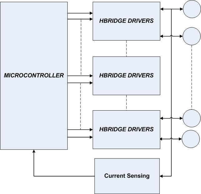
if i use DRV8833 i need to use ADC for current sensing of all 24 motors but this technique seems again which will increase number of components in the board. i need to reduce the number of components in the design, please find attached block diagram.

I need to reduce number of PWM pins of the micro-controller , number of Hbridge drivers and current sense ing circuit as well.  can you please suggest what is best way i can reduce current sensing, number of Hbridges and number of pins of micro-controller(I need to control 24 DC brushed Motor).


  • Hi Anil,

    This is a difficult question to answer because there are too many unknowns. For instance, will the motors only run in one direction; will only one motor be running at any one time, etc.

    For starters, please look at http://www.ti.com/lsds/ti/amplifiers-linear/integrated-motor-driver-products.page, which list the integrated motor drivers available.

    You may be able to use one like the DRV8823, which can drive 2 DC motors in both directions or 4 if running in one direction only. It also has a SPI interface which may help reduce pin count.

    I hope this helps point you in the right direction.

    Also, depending on the number of motors running and the need to monitor current you may be able to use an analog mux to switch the sense resistor of the running motor to the ADC.


  • Hi Rick,

    I'm working with Anil on the design (though I'm more of a software developer). I thought I'd add some info to the thread and answer some of your questions:

    * The motors will run in both directions;

    * All motors will run at the same time but be controlled by software (using position and current-sense feedback); in the most common scenario, a few motors will carry most of the load (and require the most current) - while most others will be idle or slow-moving.

    * The motors are all small, brushed DC motors (3V) - the kind you'd find is micro-servos;

    * We are using an STM32F407VG chip as our main MCU and would like to use the on-chip ADCs, if possible;

    Also, we looked at the DRV8823 - however, it's more expensive per channel in >1k units. And the package size (per channel) seems bigger (unless I'm mistaken) - requiring a larger board surface area than 24 channels using DRV8833 chips in its smallest package.

    Minimizing board size is one of our most important goals (reducing cost for >1k units is important too) - which is why we're hoping to get current sense feedback from all DRV8833s using a small number of components (e.g., ideally one current sense resistors, with one or two MUXes, etc.) - and using software to 'switch' and sample values. (We only need to sample between 500-1k times per second per motor, with 12-bit precision.)

    With this in mind, we're trying to figure out the right analog MUX that would allow us to ground the sense pins in the DRV8833s when not sampling them - but then switch to the current sense resistor when sampling. (I see this part on your site: CD74HC4067M - would using a couple of these work?)

    A couple other questions:

    * Will we be able to get reliable current sense feedback from this kind of design, considering our requirements?

    * How will the direction of the motor affect the current sense feedback from the DRV8833?

    Any guidance would be greatly appreciated. Thanks!

    Tom

  • With this in mind, we're trying to figure out the right analog MUX that would allow us to ground the sense pins in the DRV8833s when not sampling them - but then switch to the current sense resistor when sampling. (I see this part on your site: CD74HC4067M - would using a couple of these work?)

    >> The analog mux that you have selected is 70Ohms typical resistance. This will seriously impact the performace of the motor. In general, it would be preferred to have a sense resistor for each motor and an analog mux that can select which motor is being monitored. 

    If you are trying to switch in a sense resistor, there must be an alternate path (usually a transistor) without the resistor to run the motor when not sensing the current.

    A couple other questions:

    * Will we be able to get reliable current sense feedback from this kind of design, considering our requirements?

    >> Yes you can achieve reliable current sense feedback, but it may require filtering and synchronizing the measurements. If you are PWM'ing the motor, the current will increase and decrease as the outputs are enabled and disabled.

    * How will the direction of the motor affect the current sense feedback from the DRV8833?

    >> The current sense feedback is between the source of the two low side FETs and GND. Please refer to the block diagram on page 2. This allows one resistor to be used in both directions.

    Any guidance would be greatly appreciated. Thanks!

    >> Based on your description above, motor position could be your biggest challenge from a cost and board space point of view.

    Good luck with your design.

  • Hello Rick,

    I was wondering if any of our motor driver (I need a stepper one) can provide diagnostic feedback?

    Thank you,

    Natallia

  • Hi Natallia,

    What type of diagnostic feedback do you have in mind?

    Many of our motor drivers have a nFAULT pin that indicates overtemp, overcurrent, and undervoltage. Also many have a nHOME pin that can be used to indicate something has malfunctioned in the system.

    The DRV8711 has a stall indicator in addition to indicate that the stepper motor is stalled.

  • Hello Rick,

    Thank you very much for your help. They are interested in motor failure detection and outside of spike channel detection.

    Best Regards,

    Natallia

  • Rick,

    One more thing...Do we have any stepper motor drivers that are P-pap qualified? I couldnt find any online. Do we have intentions to do this qualification and/or their is a third party company that can help with it? Quality level is extremely important (medical application).

    Thank you very much for your help,

    Natallia


  • Hi Natallia,

    There are no internal diagnostics other than those listed on the datasheet.

    I am unfamiliar with P-pap qualified. Can you explain?

    For higher quality, there are a few devices stepper drviers are automotive qualified, like the DRV8823-Q1and DRV8824-Q1. 

  • Rick,

    PPAP is Product Part Approval Process (http://en.wikipedia.org/wiki/Production_part_approval_process) - it is a version of Automotive Qualification, as I know. I understand that all internal diagnostics is listed in the datasheet, but I was thinking maybe there are some app notes. Thanks a lot for your help,

    Natallia