This thread has been locked.

If you have a related question, please click the "Ask a related question" button in the top right corner. The newly created question will be automatically linked to this question.

DRV110 current control issue

Other Parts Discussed in Thread: DRV110, DRV110EVM

I have a solenoid I'm trying to interface with the DRV110 that does not seem to be working quite as I had hoped.

The solenoid electrical specs are as follows:  3.3V nominal operating, ~10.70 ohm coil, 5mH inductance, roughly 325mA to open with a hold current of 75mA.

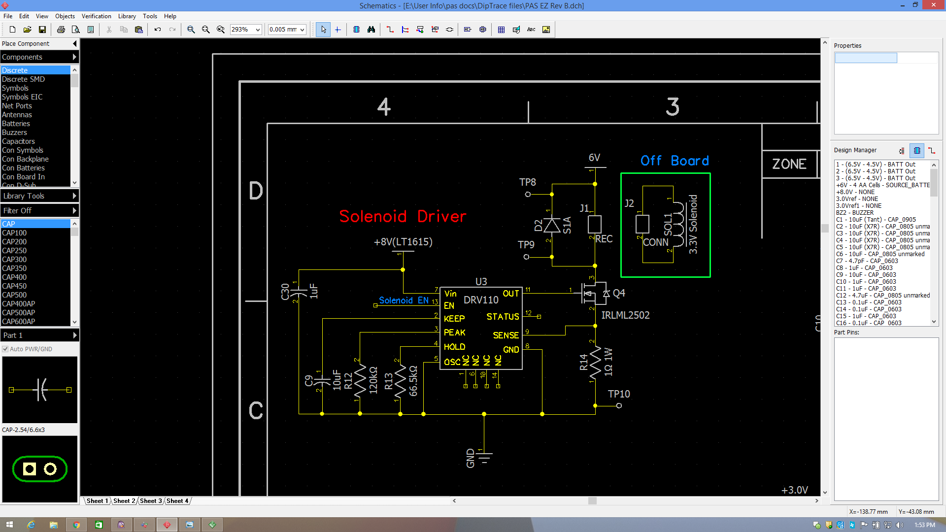
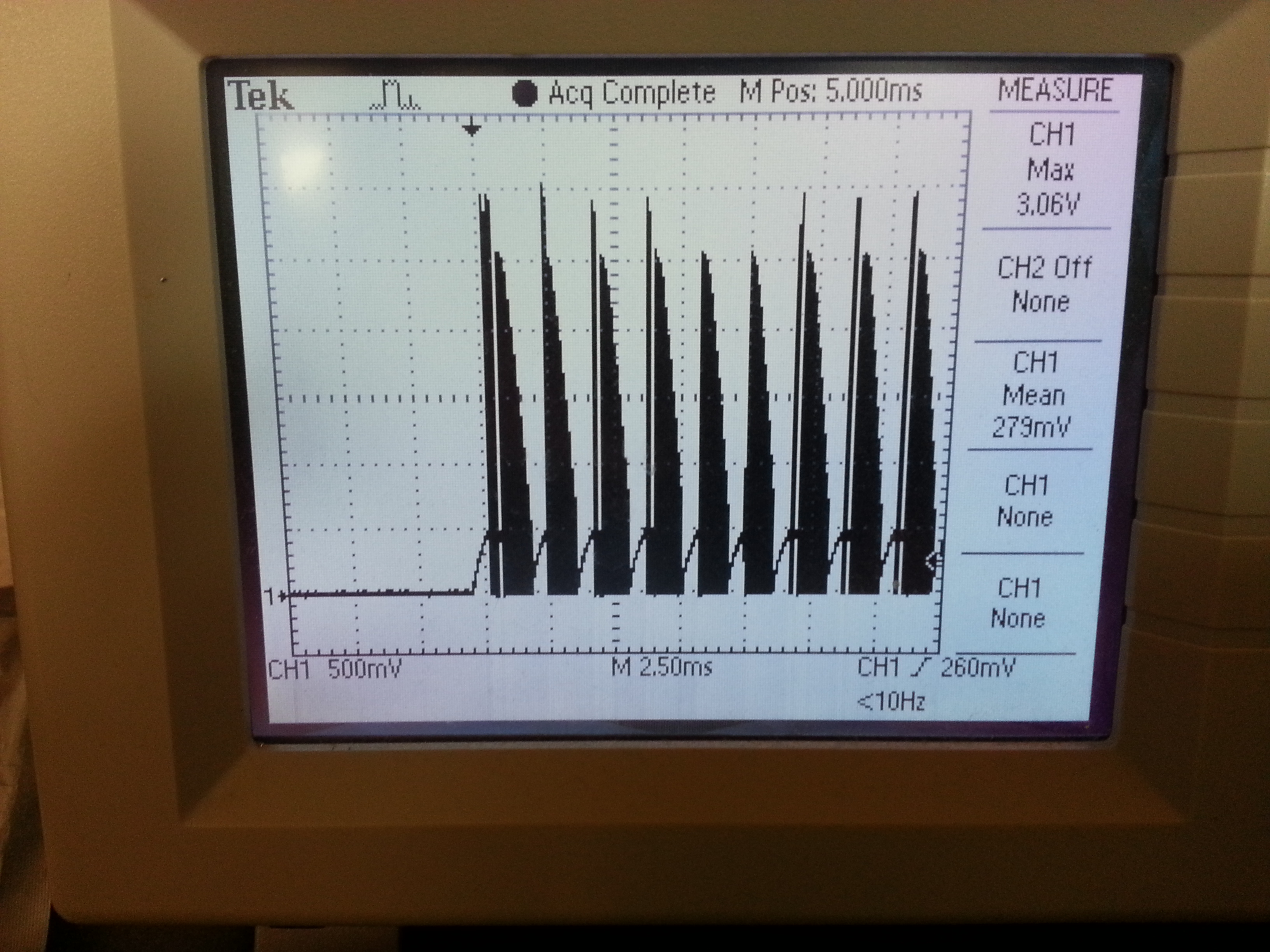
Attached is the schematic of the solenoid driver circuit I'm using. With the external components I selected I should see a 1sec peak time at 500mA, followed by a 150mA hold. The solenoid opens most of the time, although it struggles at times. Attached is a pic of the voltage across the sense resistor at the start of the peak fire. If the mean voltage value is accurate(~280mV) then the voltage reference across the 1ohm resistor is producing ~280mA worth of current. This would account for the struggling opening. 

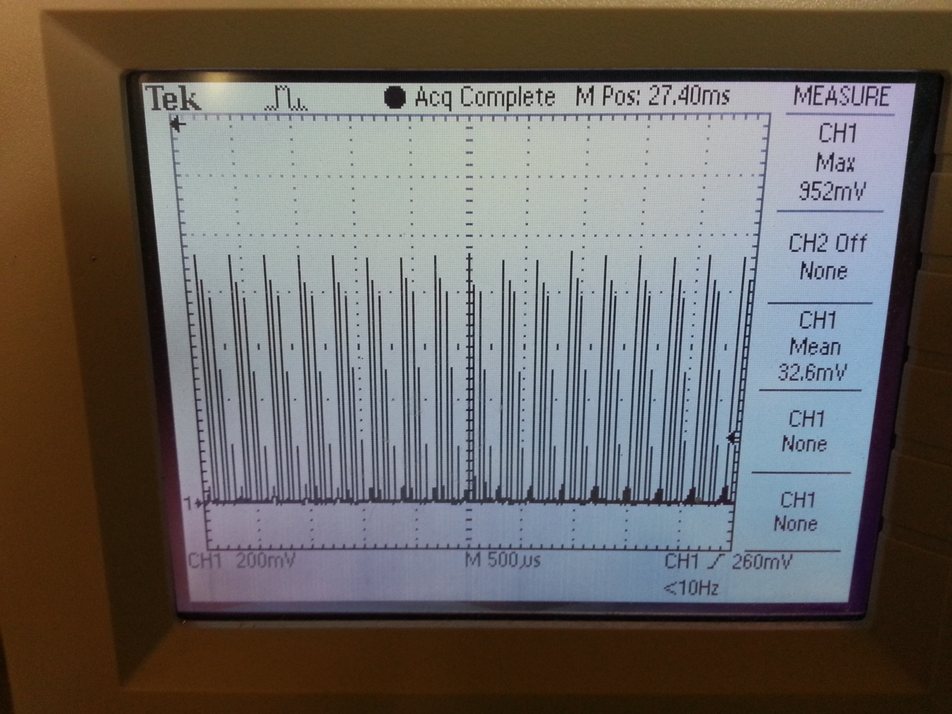
Also attached is a pic of a portion of the hold sequence voltage across the sense resistor. With a mean of 32mV it correlates to the measured current of the solenoid of approximately ~30mA during the hold sequence that I'm seeing. The solenoid immediately closes once the peak time ends due to the hold current being too low.

Could there be a layout issue that's skewing the sense pin's voltage reference?
Initial peak fire:
Hold portion:
  • Hi Jason,

    Our experts have been notified and should reply soon.
  • Jason,

    Thank you for providing very good details.

    As long as the passives are close to the chip, I don't think there should be any issue from layout.

    One thing you can try is putting an RC filter between the sense resistor and the SENSE pin. The DRV110EVM User Guide (http://www.ti.com/lit/ug/slvu686b/slvu686b.pdf) shows where to put it in the schematic. You can try doing this with larger values of capacitance too.

    Check the voltage at the OUT pin too. Some FETs with a high gate capacitance will take a long time to charge. However, I looked at your FET's datasheet, and you should be fine there, but it's another thing you can check to see if it is functioning properly.

  • James, 

    Thanks for your help suggesting the low pass filter. I designed my own development board to do some testing and troubleshooting with my design. 

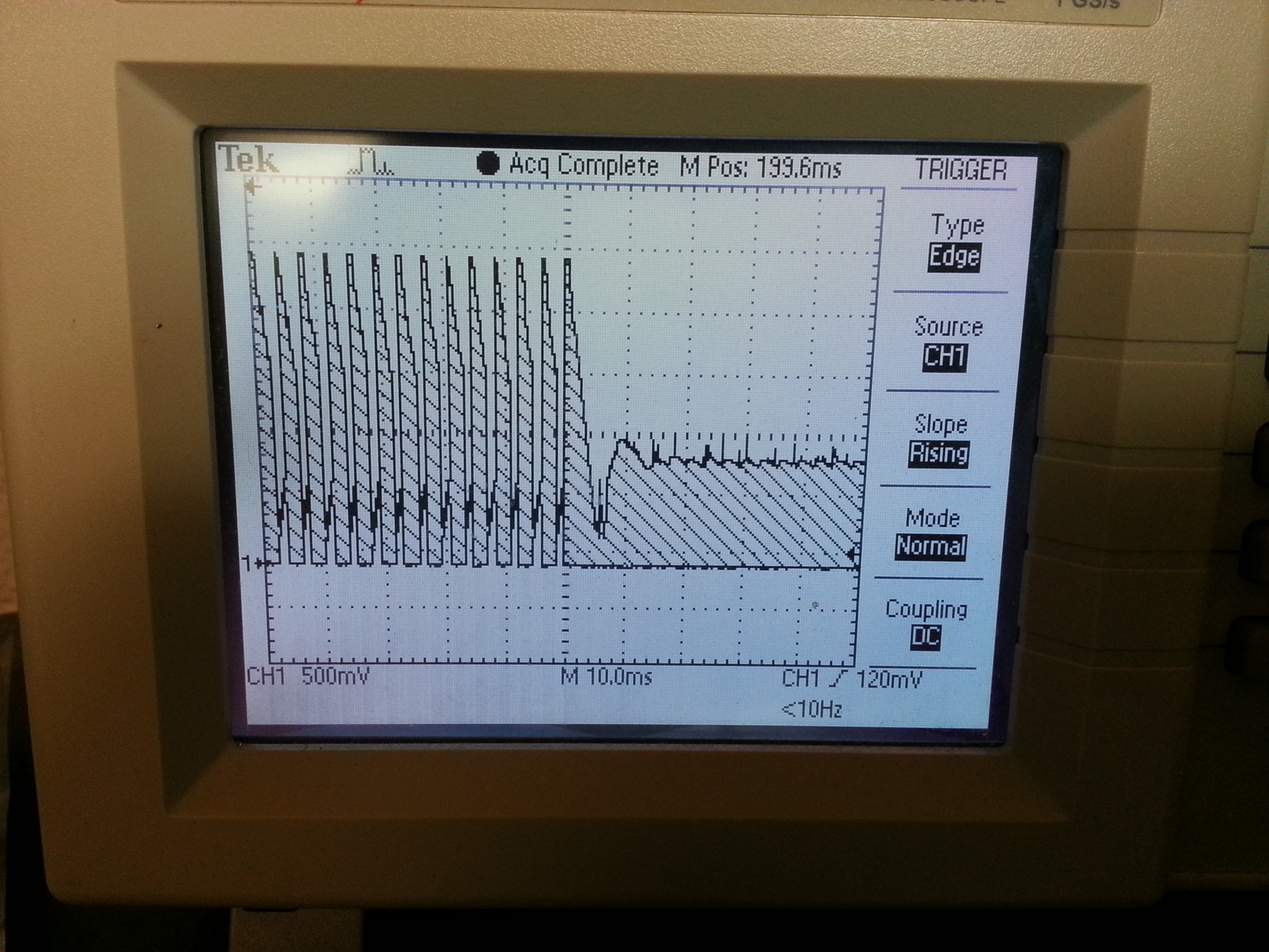
    First and foremost the current regulation is dead on for both peak and hold portions of the control scheme, but I was still having an issue with the solenoid returning to its normal position during the transition from peak to hold. And here is voltage across the sense resistor. You can see where it transitions from peak to hold it would drop out, and the solenoid would return back to it's normal position. This is without a low pass filter installed.

    I installed a low pass filter, which required over 220pF of capacitance for proper function, and now it transitions flawlessly from peak to hold. Here's what the transition looks like now with the low pass filter:

    Thanks for TI's support on this,

    Regards,

    Jason Bonner

  • Jason,

    I'm glad to hear my suggestion helped! If your solenoid is returning to its original position, then my guess is that the hold current is set too low. Try increasing it.

    The TI Design note at this link (http://www.ti.com/lit/ug/tidu584/tidu584.pdf) recommends setting I_HOLD to 35% of I_PEAK. However, this is a rule of thumb, and all solenoids are created differently. If you have a datasheet for your solenoid that you can send me, I can see if it gives any good hints for a recommended hold current.

    I would also like to ask you a favor. You said that you developed your own evaluation board for testing the DRV110. I have heard this feedback from several customers on E2E. I am thinking about re-making the evaluation modules for the DRV110. Can you please give me some suggestions for what you would like to see in a new evaluation board? What were your reasons for deciding not to purchase the one we offer? I would be interested to see your board if you could send schematics/layout/pictures.

  • James,

    I have the hold current set to max of 150mA, and the DRV110 is regulating that well. It was the drop out that was occurring on the peak to hold transition prior to the low pass filter install that was causing the solenoid to return to its original position. Once the filter was installed that dropout disappeared and the solenoid remained in its powered position.

    The reason I designed my own evaluation module was because I wanted all the power supply parts that I'm using in my prototype to be included for testing in the development board. The product I'm designing is a handheld device that operates from 6-4.5V, and I have a boost converter driving the DRV110, but battery supplying power to the 3.3V solenoid I'm using. I also have the boost converter supplying solenoid power as well for testing purposes if needed, so I'm easily able to switch solenoid power supplies. There are some other variances as well, but that was the main purpose.

    I'm not sure what other recommendations I can make to TI's current evaluation module other than perhaps some openings to add resistors/capacitors to change the low pass filter configuration on the sense pin, which is also something I did on mine.  

  • I misread your previous post and thought you were still experiencing an issue with the device. Let me know if you have any other questions.

    Also, thanks for helping me understand your application. Good luck with your design!