This thread has been locked.

If you have a related question, please click the "Ask a related question" button in the top right corner. The newly created question will be automatically linked to this question.

DRV2605L: In RTP mode, the maximum value is 127 (0x7F) only

Part Number: DRV2605L
Other Parts Discussed in Thread: TCA9554, TCA9548A,

Hi Team,

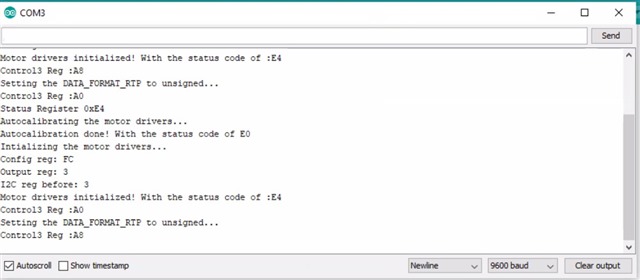
According to the customer, when running the DRV2605L motor drivers in RTP mode, the maximum value they could use is 127 (0x7F). When they changed the sign bit to unsigned so that they have higher integer values in Control3 register (address 0x1D) they couldn`t run the motors. Is there any register they need to configure aside from Control3 register?

Thank you for your support!

Regards,

Danilo

  • Hello Danilo, 

    I have a few questions for you regarding this:

    1. Are they running the DRV2605L in bidirectional or unidirectional mode?
    2. Is this closed or open loop? 
    3. What are they using for an RTP_INPUT value 

    Thank you, 

    Justin Beigel

  • Hi Justin,

    Here are the customer's response.

    1. Are they running the DRV2605L in bidirectional or unidirectional mode? Ans. Running in bidirectional mode
    2. Is this closed or open loop? Ans. closed loop
    3. What are they using for an RTP_INPUT value? Rtp=0×7F

    Here is the code provided by the customer.

    #include <Sparkfun_DRV2605L.h> //SparkFun Haptic Motor Driver Library
    #include <DRV2605LEVM_MD.h>
    #include <Wire.h> //I2C library

    SFE_HMD_DRV2605L HMD; //Create haptic motor driver object
    DRV2605LEVM_MD multi_drv; //Create multi motor driver object

    void setup()
    {
    Serial.begin(9600);
    HMD.begin();

    Serial.println("Autocalibrating the motor drivers...");
    // Start autocalibration by setting the GO bit to 1
    HMD.go();
    HMD.Mode(0x07);
    Serial.println("Autocalibration done! Intializing the motor drivers...");
    // HMD.Mode(0); // Internal trigger input mode -- Must use the GO() function to trigger playback.
    HMD.Mode(0x05); // RTP Mode -- Must use the RTP function to trigger amplitude.
    HMD.MotorSelect(0xB6); // LRA motor, 4x Braking, Medium loop gain, 1.365x back EMF gain
    HMD.Library(6); //1-5 & 7 for ERM motors, 6 for LRA motors

    multi_drv.initialize_motors();
    Serial.println("Motor drivers initialized!");


    }
    void loop()
    {

    HMD.RTP(0x7F);
    delay(5

    Regards,

    Danilo

  • Hello Danilo, 

    Thank you for the additional information. Based on the code, is this using the DRV2605LEVM_MD or are they just using the code for their own board? 

    Also, in the code, I don't actually see where the Data_Format_RTP bit in Control3 register is getting written to. Can you clarify this? 

    For the autocalibration, it would be best to set the device in autocalibration mode (HMD.Mode(0x07)) before setting the GO bit to 1. 

    Thank you, 

    Justin Beigel

  • Hi Justin,

    We have received the response of the customer below.

    We are using our custom library, named “DRV2605LEVM_MD” for communicating with the TCA9554 and TCA9548A devices and we use Sparkfun’s “Sparkfun_DRV2605L” library for communicating with the DRV2605L motor drivers.
    The answers to your questions:
    1. Unidirectional or Bidirectonal?
    • We are using the default setting. Should we use the unidirectional?
    2. Is this closed or open loop?
    • Again, we were using the default setting for RTP. We are not sure which mode we should use. What are your suggestions?
    3. What are they using for an “RTP_INPUT” value.
    • We were sending “0x7F”. The motor does not vibrate with a value higher than “0x7F”.
    • When we change the “DATA_FORMAT_RTP” field of the “Control3 Register (0x1D)” to “Unsigned”, no value for “RTP_INPUT” makes the motor vibrate.
    • So that why we removed that line from the code but we were changing this through the Sparkfun’s library using the command:
    • HMD. writeDRV2605L(CONTROL3_REG, 0xA8)

    One thing we can elaborate is, when we start communicating with the DRV2605LEVM-MD board, from the status register we are getting “E4”. I think it means “Feedback controller timed out” but we didn’t understand what it meant? Is it OK to have that status/error message? What should we do?

    Regards,

    Danilo

  • Hello Danilo, 

    There is no need to change the configuration for 1 or 2, it was just so I know how to best help here. The "E4" value is not a problem and shouldn't be causing issues at startup. If you read the status register after attempting to play a waveform, does it give the same value? 

    I am still working to recreate this issue and will keep you updated as I make progress. 

    Best, 

    Justin Beigel

  • Hi Justin,

    Thank you for your feedback. We will wait for your updates.

    Regards,

    Danilo

  • Hi Justin,

    Here is the code from the customer.

    DRV2605LEVM_MD.zip

    Regards,

    Danilo

  • Hello Danilo, 

    I have not been able to reproduce the issue. I setup an EVM in the same configuration and set the DATA_FORMAT_RTP to Unsigned. Can you have the customer read the 0x1D register after they write it to make sure that the value is properly getting updated? Also, are there any issue if an auto calibration is run? 

    Thank you, 

    Justin Beigel

  • Hi Justin,

    Here is the feedback from the customer.

    The customer is using Arduino Uno and connected it thru the SDA and SCL lines of TCA9548APW of the DRV2605LEVM-MD as I have mentioned in another thread below.

    https://e2e.ti.com/support/motor-drivers/f/motor-drivers-forum/989055/drv2605levm-md-port-the-drv2605levm-md-firmware-v1-3-rev-a-from-the-product-page-of-drv2605levm-md-to-arduino-mega

    Regards,

    Danilo

  • Hello Danilo, 

    I am double checking something with my colleague for this and will get back to you tomorrow. 

    Best Regards, 

    Justin Beigel

  • Hi Danilo, 

    Just wanted to give you an update. I was able to acquire everything I need to replicate your setup and will be testing tomorrow to figure this issue out. 

    Best Regards, 

    Justin Beigel

  • Hello Danilo, 

    After some testing, I think the EVM startup is changing some of the register configurations and you need to specifically write them in the code to make sure they are in the correct state. I was able to get the code to work by adding in just a control2 register write. I wrote the device into unidirectional mode but it could be put in bidirectional by changing the write to 0xFF instead. 

    HMD. writeDRV2605L(CONTROL2_REG, 0x7F); // Unidirectional Mode

    Let me know if you have any other questions. 

    Best Regards, 

    Justin Beigel