This thread has been locked.

If you have a related question, please click the "Ask a related question" button in the top right corner. The newly created question will be automatically linked to this question.

DRV8320: IDRIVE AND VDS PIN OF DRV8320H

Part Number: DRV8320
Other Parts Discussed in Thread: CSD18540Q5B

Hi,

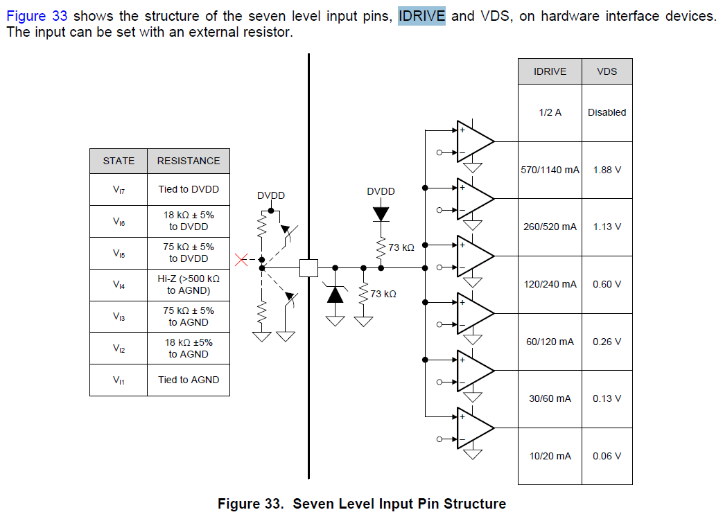
I want to control a BLDC Motor with using DRV8320H as a driver. Also in Mosfet part, I decided to use CSD18540Q5B. But I couldn't calculate what to connect to the IDRIVE pin.

Formula : IDRIVEP > Qgd / tr    IDRIVEN> Qgd / tf

  • Hello,

    The IDRIVE pin controls the MOSFET VDS slew rates which is a critical factor for optimizing radiated emissions, energy, and duration of diode recovery spikes, dV/dt gate turn-on resulting in shoot-through, and switching voltage transients related to parasitic in the external half-bridge.

    First step, get Qgd value from the datasheet.

    2nd step, decide the tr and tf value to optimizing radiated emissions and PWM power stage efficiency. Slow down rising edge and falling on SW node can make the high frequencies noise roll off more quickly with 40dB/dec  and reduce EMI noise ().  One previous test case showed the EMI noise was reduced 15dB when the VDS slew rate was changed from 7ns to 20ns.  To me, please control the tr and tf at least longer than 20ns for motor drive which also has enough margin to Tdrive (500ns, 1us, 2us, 4us). In the datasheet, an example uses 100~300ns for tr and  50~150ns for tf. I also agree with that range for motor drive control.

    After you have Qgd and tr and tf number, you can have IDRIVEP and IDRVEN. Pick a IDRIVE current slight lower than Figure 33 table.

    Also, an application report "Understanding IDRIVE and TDRIVE In TI Motor Gate Drivers application report" () gives the detail about the MOSFET Qgd, IDRIVE pin calculation consideration and some test waveforms as reference.