This thread has been locked.

If you have a related question, please click the "Ask a related question" button in the top right corner. The newly created question will be automatically linked to this question.

Wheatstone Bridge Resistance

Hi,

I am puzzled by my measurements on Wheatstone Bridge ! I measured vout of two separated 1/2 Bridges. Then I subtracted them to obtain Vout difference. Then, I measured the leg of each 1/2 Bridges as well and I calculated the Vout difference of Bridges, using the measured resistances (applying voltage divider rule). I am surprised that the measured Vout difference and the calculated Vout difference are very different. I appreciate any idea. Thanks

  • Hi Nader,

    Thanks for reaching out to us. My name is Mamadou Diallo, I will help you resolve this issue.

    Can you please share the device for which you're attempting to measure the resistance of the bridge. Additionally, can you post schematic with the points where you are measuring those resistance values that you described?

    Any further details on your application and our device that you're using would be very helpful.

    Regards,

    -Mamadou
  • Nader,

    Tell me about your voltage meter. Did it change the voltage while measuring the voltage (current flowed through the meter)?
    Tell me about measuring the resistance. Was the bridge powered off and removed from other circuits? Did your skin touch the leads or bridge in more than one place (parallel resistance paths)?
  •  Hi Mamadou, measurement setup  is attached. Thanks

  • The PS shows 5.005 volts, but, when I measured the PS output, using DVM(before setting up the test), it shows 5.05 V. I am guessing that PS display is not very accurate ! right ? But even this .05 V difference in reading does not nearly explains the discrepancy I am experiencing. When i did measure the resistances , the system was not energized, as shown in my set up picture. I dont think I created any parallel path. Thanks
  • Hi Nader,

    Thanks for the updates!

    It sounds like your bridge is not balanced. Any variation in resistance would create a differential voltage at bridge's output. I am suspecting that R1 R2 R3 and R4 are not equal. Measure those resistances value before even powering your application and let me know what you get. 

    Additionally, I would suggest measuring Node A to Node C AND Node B to Node C and taking their difference for the Vout of the bridge. 

    Or if you have a differential probe, you can measure directly from Node A to Node B.

    Regards, 

    -Mamadou

  • Hi Mamadou, I appreciate your follow up, but I think you did not get my point and my problem. Yes, the bridge is not balanced. Each leg has a different resistance. Please read my original message one more time and you will see that my concern is something else. The problem is I MEASURED the output of the bridge and then compared it with CALCULATED output (using measured individual bridge leg resistances, then calculated Vout, using voltage divider method). The MEASURED and CALCULATED Vout did not match, there is a big difference. I don't know where this discrepancy is coming from. Please let me know if more info is needed. Thanks
  • Nader,

    Please show us your values for resistors and measured voltages.
    'Big difference' is a vague term and finding the issue requires the data.
    In addition to node A-B voltage data, node A to ground and B to ground is useful.
  • Exit Voltage = 5 VDC

    Measured differential Vout = 1.699 mV


    R1

    3532

    R2

    3603

    R3

    3189

    R4

    3240


    Calculated differential Vout = 5*(3603/(3603+3532)-3240/(3240+3189)) = 5 mV !


  • Nader,

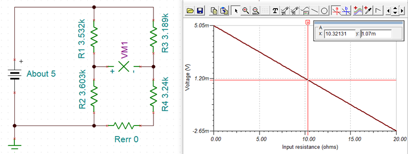
    To get this output difference would require a 10 ohm change in one of the resistors (not certain which one or if it's a combination of more than one)

    A wheatstone bridge using fixed resistors is not useful. Are any of the resistors intentionally sensitive to temperature, physical stress, or something else?

    An output of 1.7mV is a better balance than the calculated 5mV. Maybe 1.7mV is the correct answer and the resistor measurements do not reflect the connected result situation.

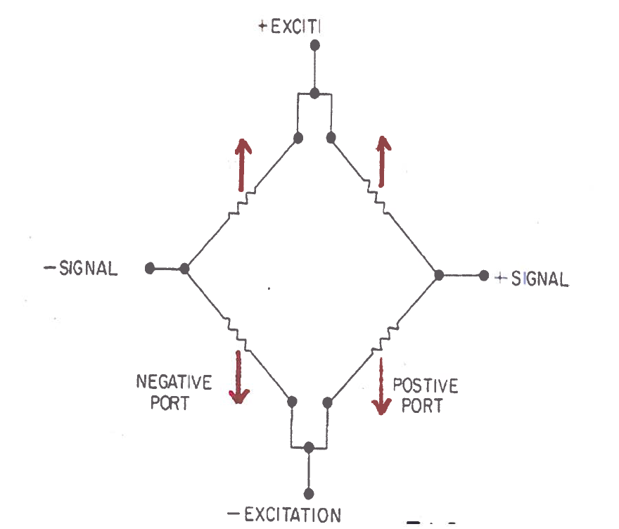
    Note that the tie together for the half bridges need to happen at the bridge not the power source.   

  • Hi Ron,

    Thank you for the simulation and shedding a new light to the problem. I ran your simulation in Papice Orcad, using parametric sweep. I got the same result as yours. This 10 Ohms or any resistance causing  imbalance could have come from long wires in my setup. This bridge is, in fact, representing a thin film bridge pressure sensor. The bridge would go under temp and pressure. However,  I need to eliminate the temp effect. So, I need to compensate this circuit for temp effect. For this purpose I need to find the characteristics of this bridge, i.e., values of all four bridge legs. These resitance values will be entered in a set of 3 equations to come up with the values of compensation resistors. Any way, thank you for clarifying the point that a small resistance imbalance could cause large voltage difference, just because in measuring the bridge voltage difference, the common mode gets eliminated.

    Everyone, sorry for ambiguity in describing my problem. 

    Thanks