This thread has been locked.

If you have a related question, please click the "Ask a related question" button in the top right corner. The newly created question will be automatically linked to this question.

ADS7845: ADS7845 - DOUT 12bit all High when the panel be touched.

Part Number: ADS7845

Hi experts,

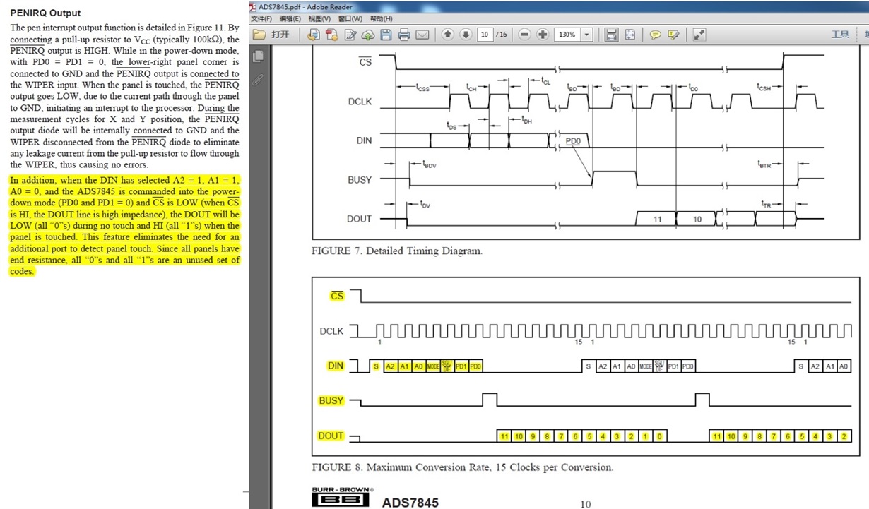
We are testing our ADS7845, but we found the datasheet mentioned: the DOUT will be 12bit all High when the panel be touched. datasheet Page 12.

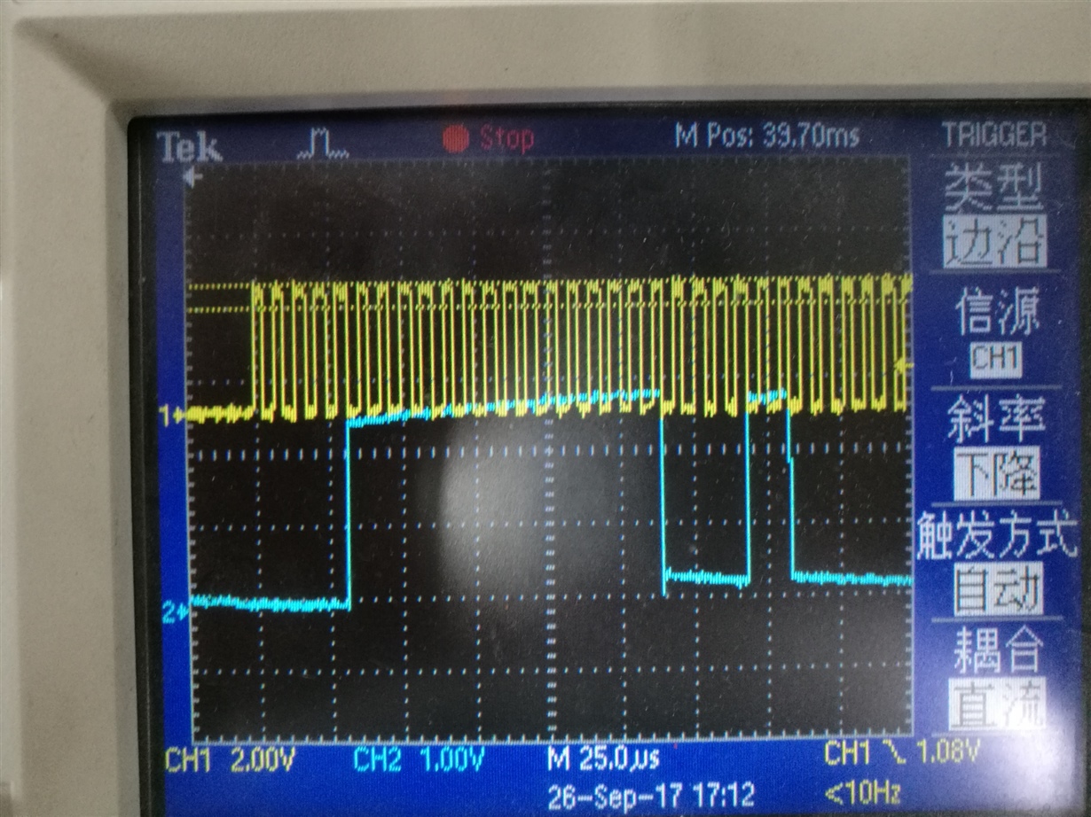
But during the test in customer's board, we found the MSB 11bit is all high, but the last LSB bit[0]=low.

So could you please help double confirm whether customer's board is something wrong or ? thanks.

Best Regards

Iven Xu

  • Hi Iven,

    Please make sure that they the 100k pullup resistor for PENIRQ to Vcc. 

    Also check that they are writing A2, A1, A0 = 111 and PD0 and PD1 = 0. 

    CS must also be low.

    Mike

  • Hi Mike,

    thanks for your reply, so our datasheet is correct and all 12bit should be high when the panel be touched, right?

    and do you think there should be something wrong only related the A2 A1 A0 PD0 and PD1? thanks.

    Best Regards

    Iven

  • Hi Iven,

    Yes, the datasheet is correct. In my post above I list the values for A0-A2 wrong. They should be A2, A1, A0 = 110. The datasheet is specific that these bits be those values along with PD0 and PD1 = 0. They the 100k pullup resistor for PENIRQ to Vcc?

    Mike
  • Hi Mike,

    for your previous suggestion:
    Please make sure that they the 100k pullup resistor for PENIRQ to Vcc.
    -> yes, confirmed that they have this 100Kohm pull up resistor
    Also check that they are writing A2, A1, A0 = 111 and PD0 and PD1 = 0.
    -> could you please confirm is it A2, A1, A0 = 111? but it is 110 on our datasheet.
    CS must also be low.
    -> yes, confirmed the CS is low.


    Best Regards
    Iven Xu
  • one more thing,

    the command they used to detect the touch: 0xE0


    Best Regards
    Iven
  • Hi Iven,

    That is correct A2, A1, A0 = 110. 

    The command that they send of 0xE0 (1110 0000) should be ok. 

    Some things to try. 

    Bring CS low.  Start the clock and send the command data of 0xE0 (1110 0000).  Keep CS low and keep the clock running.  Does any data come back periodically from the ADS7845?

    Could they also try 0xE4 (1110 0100) just to see if that makes any difference?

    Could you send me the schematic?

    Also, could you send me the scope shots of the data write to the part and the data out?

    Thanks,

    Mike

  • Hi Mike,

    1, Bring CS low, start the clock and send the command data of 0XE0 or 0XE4, keep cs low and keep clock runining.
    if do not send the more command (means only send this 0xE0 or 0xE4), then the Dout is 0xFF.
    But in customer's application, after send the command data of 0xE0 or 0xE4 to do the touch detection, then they need to send the following two commands to detect the X data and the Y data, and customer have follow up the figure 8 timing format in datasheet page 10, which means the second command of the X data detection will be sent out at the 16th clock(at this timimg clock, the first Dout of the touch detection is just on the 6th bit), than they read the Dout of the touch detection is 0xFE, the last bit is changed to 0.

    But they found the following Dout for the X data and Y data is correct.

    So they have concern, could you please help verify the Dout with Figure 8 of page 10?

    sch:

    Dout vs. Dclk: you can check with figure 8 of page 10, and the 10th dclk rising is the bit 11 of Dout, and you can see the Dout is H only from bit 11 to bit 1, and the last bit 0 is 0.

    channel 1 is Dclk, channel 2 is Dout.


    Best Regards
    Iven

  • Hi Mike,

    one more assuption: if the Dout is 0xFE with the timing of figure 8 on page 10, than they can use 0xFE to to the touch detection.
    But the concern is, our datasheet is 0xFF for touch detection. So it need your help to do the verification. thanks.


    Best Regards
    Iven
  • Hi Iven,

    You say above that they send data of 0xE0 or 0xE4, keep CS low and keep clock running and they get data back of 0xFF. They do not send other commands. This is the correct operation. When you send the command of 0xE0 or 0xE4 (to set up the part to monitor if the touch screen is touched or not) you do not send other commands. You get back 0xFF if the screen is being touched and 0x00 if the screen is not being touched. This mode is used only to alert the controller to detect when a touch has happened, not to give the actual touch data. Once the controller has received data of 0xFF, which means the screen is touched, then you can send the commands to get the x and y data.

    You should not send the 0xE0 or 0xE4 commands and then other commands as you mentioned above and then wait for 0xFF data for a touch. You will not get 0xFF data because you have overwritten the 0xE0 or 0xE4 commands.

    Mike
  • Hi Mike,

    1, So based on your explanation, customer need to wait all 12bit Dout be sent out completely after send the command 0xE0 or 0xE4, then send the other command, right?

    2, if right, how to explain the figure 8 on page 10 of ADS7845 datasheet? this is the main concern from customer.

    becuase from the figure 8 on page 10 of ADS7845 datasheet, it only need to wait 15 dclk after the first command, then they can send out the second command. it looks the first Dout have not been sent out completely during the second command start to be sent out.

    Please comments? thansk.

    Best Regards

    Iven Xu

  • Hi Iven,

    Figure 8 is a special case the the ADS7845 can run in. Normal mode is like Figure 5 (24 clocks) or Figure 6 (16 clocks). The ADS7845 can run with 15 clocks per conversion. This is not the normal way that most customers use it, because most microcontrollers can't do 15 clock per transfer. You can use this method if you are using a master that can provide 15 clocks per conversion like an FPGA or ASIC. Please see the 15 Clocks per conversion paragraph on page 10.

    Mike
  • Hi Mike,

    thanks for your clearify, we have verified on the board if increae to 16 clocks per conversion.
    I think it might becuase of the timing of DCLK from the FPGA(We are using), even we are using a FPGA. So I think we don't need pay more effor on this case and let's close it. thanks.


    Best Regards
    Iven