Other Parts Discussed in Thread: MSP430F5131, BQ25120
Hello Everyone,
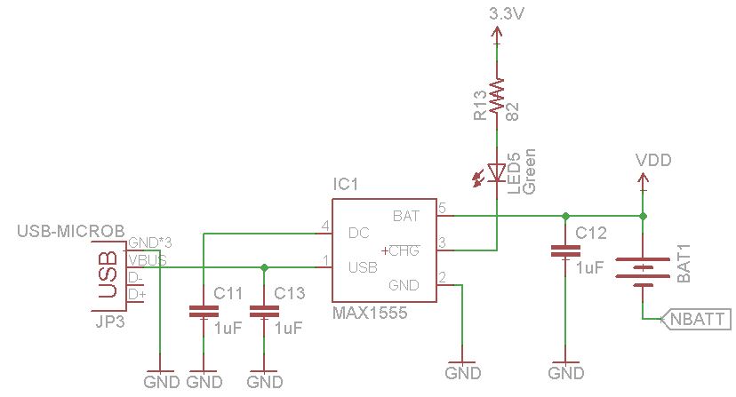
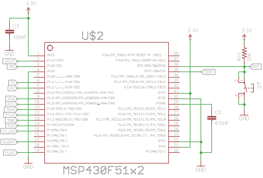
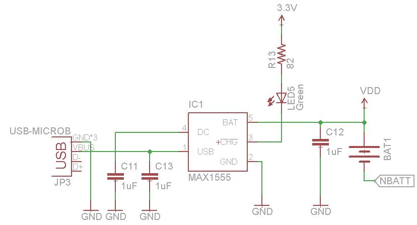
I am designing a circuit that uses the MSP430F5131 as the MCU. The board will be powered by a 3.6V Li-Ion coin cell battery. I have a charging IC (MAX1555) but it outputs about 4.2V to the load while it charges the battery via USB. Most of the charger ICs I have found behave the same way. All the other components can operate within that voltage range except the MCU. Can anyone suggest a solution on how to solve this problem? Here are some of my thoughts:
- Use a forward biased diode to drop down the voltage (about 0.7V). But this won't work so well since I'm trying to learn low-power designs.
- Use a PFET to isolate the battery from the load. Have the CHG pin from MAX1555 control the GATE pin to allow power to the load when the battery is done charging. But there is still a diode voltage drop as well.
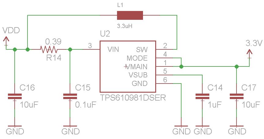
- Use a DC-DC converter after the battery to keep the voltage fixed to 3.3V (or 3V)
- Choose a different MCU or battery charging IC
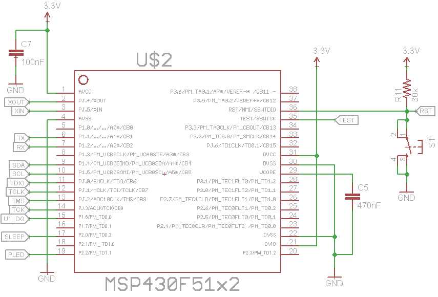
I would really rather not pick a new MCU, but if that's the best option then I'll do it. I would appreciate any input you guys have to offer. I have attached some images of the current schematic below. If you have any questions or comments, please feel free to ask.
Anson
EDIT UPDATE: