


Other Parts Discussed in Thread: BQ76952, BQSTUDIO
Hi,TI`s Team;
When the single cell voltage is greater than the COV threshold, the COV Safety Alert registere goes high,but after COV delay time,the COV safety status A register doesn't go high,When I adjust the single cell voltage to a higher level, the COV status register will go high;
Why the actual protection value in test is greater than the set value in the configuration;
The following is my COV parameter configuration, when I increase the voltage to COV threshold and higher,we can find the voltage when the warning register go high , and the voltage when the status register go high;
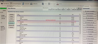
parameter configuration
when the single cell voltage is4.196V,the COV safety status does not go high;

when the cell voltage is 4.237V,the cov status goes high


