This thread has been locked.

If you have a related question, please click the "Ask a related question" button in the top right corner. The newly created question will be automatically linked to this question.

TPS92518-Q1: The output current varies with respect to the input voltage

Part Number: TPS92518-Q1
Other Parts Discussed in Thread: TPS92518

Hi Team,

We would like to ask your help regarding the customer's inquiry below.

We are using the TPS92518 controller in our automotive application. Our conditions are as follows:

Vin = 9..32V
Vled = 2..12V
Iout = 20..100mA

Under these conditions, we decided on the following component values for the inductance and the R_Sense:

L = 330uH -> I_PEAK_PEAK approx. 30mA
R_Sense = 2.2 Ohm

This should resolve Iout over the range 0-115mA and the converter should operate in CCM.

Now we find that the lower the output current is selected, the more it depends on the input voltage. This means that with an expected Iout of 20mA at Vin of 30V, we measure an Iout of 30mA. At Vin = 9V, we measure Iout = 18mA.

Q1: Is this because the controller is not designed for currents in this range?
Q2: Is the design of the component values wrong? 

Regards,

Danilo

  • Hello Danilo,

    Can I get the LEDx_TOFF_DAC setting being used as well as the LED_PKTH_DAC setting in either decimal or hexidecimal (I back calculated and get about 21 decimal for LEDx_TOFF_DAC)?

    If Ipeakpeak is 30 mA going below 15 mA average the inductor current will become discontinuous.  This is fine however dimming below this level becomes non-linear.

    I would have to know the values of the design so I can calculate the operation over Vin/Vout range.

    Best Regards,

  • Hello Irwin,

    Thank you for the answer.

    The LEDx_TOFF_DAC is set to 22 decimal.

    Our output current should be adjustable via the LED_PKTH_DAC (analogue dimming). It is therefore in the range of 78..255 decimal (20mA..100mA I_out_average or 35..115mA I_out_peak).

    Best Regards,

    Matthias

  • Hi Matthias,

    I calculated your design on the above information (see below).  It seems that it should have continuous current, average low at 19.85 mA and average high at 100.3 mA with 31.2 mA of peak to peak current ripple.

    What are the part numbers of the MOSFET, Freewheel diode, inductor and current sense resistor you are using?  On your above test what was the LED voltage (output voltage)?  I used 6V for the calculations.  Have you looked at any waveforms with an oscilloscope to see how it is operating?  I would check the switch node to see if the waveform is consistent at high and low input voltage (the on-time will change between high and low input voltage).  The switching frequency would be one to check to see if it is near what is should be and I can calculate that by changing the excel sheet I created.  Also the current sense resistor voltage would be good to look at.

    Vinlow 9 V  
    Vinhigh 30 V 9-32 is range
    Ioutlow 0.02 A  
    Iouthigh 0.1 A  
    Vledlow 2 V  
    Vledhigh 12 V  
    Vledcalc 6 V  
    Lind 0.00033 H  
    Rcs 2.2 ohm  
    LEDtoffdac 22 dec  
    LEDpkdacL 78 dec  
    LEDpkdacH 255 dec  
    Vcsl 0.078 V  
    Vcsh 0.255 V  
    IpkL 0.035454545 A  
    IpkH 0.115909091 A  
    toff 1.7166E-06 sec  
    dutyl 0.666666667    
    dutyh 0.2    
    tonl 3.43321E-06 sec  
    tonh 4.29151E-07 sec  
    dioff 0.031210986 Apk  
    dionl 0.031210986 Apk  
    dionh 0.031210986 Apk  
    Iavel 0.019849052 Aave  
    Fswl 194181.8182 Hz  
    Fswh 466036.3636 Hz  
    Iaveh 0.100303598 Aave  

    Best Regards,

  • Hi Irwin,

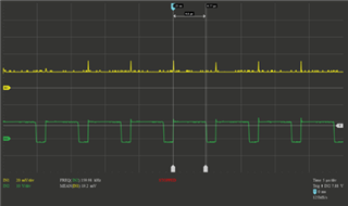
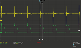
    First I measured the I_out via a shunt at the output (yellow 1mV = 1mA). The green curve represents the waveform of the switching node. 

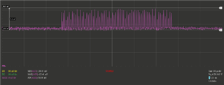
    The second measurement shows the voltage drop across R_Sense.

    The measurements are carried out with an output voltage of 6.6V. The output voltage changes up to 7.3V when the input voltage is changed from 9V to 30V.

    LED_PKTH_DAC = 78 (20mA)

    V_In = 9V:

    1.

    f = 160kHz

    D = 0.77

    I_out = 19.2mA

    V_out = 6.6V

    2. Voltage over R_sense = 2.2Ohm

    Here you can see that the voltage drop follows the expected course. The measured V_peak = 78mV

    V_in = 30V

    1.

    f = 616kHz

    D = 0.20

    I_out = 33mA

    V_out = 7.3V

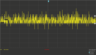
    2.

    Here it was not possible for me to carry out an evaluable measurement. But still if you ignore the peaks and the inaccuracy of the resolution of my oscilloscope due to my measurement (for this measurement a resolution of 49mV per step), it is still close to 78mV peaks.

  • Hello Matthias,

    Thank you for the scope pictures.  Notice on the switch node waveform at 30V input that the fall time fall-time is longer than at 9V input?  What I believe is happening is at low current the switch node cannot slew very fast causing an increase in average current.  When the TPS92518 reaches peak current threshold the MOSFET turns off.  The inductor is still seeing voltage applied to it as the switching node is slewing down creating an actual higher peak current.  Also the off-time starts when the peak current threshold is met creating a shorter time for the inductor current to fall (when the freewheel diode is conducting).  These two things will make the average current higher.

    What are the part numbers of the MOSFET, Freewheel diode, inductor and current sense resistor you are using?  Do you have a schematic of your design?

    Best Regards,

  • Yes, indeed. That explains the increased average current.
    Here are the part numbers:

    MOSFET: DMT10H072LFDFQ

    Freewheel diode: SS1FH10

    Inductor: SRN4018-331M

    Current sense resistor: 2.2Ohm resistor with tolerance 1%

  • Hi Matthias,

    So I can't find all the information such as the winding capacitance of the inductor however I think the MOSFET is probably dominate here.  If you look at Coss on the datasheet from 30V down to zero I took a low value of 200 pF.  The freewheel diode also has some capacitance so it will add to this but just using 200 pF and the peak current of 35.5 mA and 30V I get a slew time of 170 ns.  I can't see the time base of the scope picture above to compare however at 500 KHz that is 8.5% of the switching period.  It will be more due to the diode and MOSFET non linear Coss.

    The MOSFET is definitely too large for this current level.  even at 100% on-time the conduction loss is less than 1 mW at 100 mA.  The diode is on the large side as well.

    I'd fine parts with lower parasitic capacitance and possibly design for lower switching frequency (larger inductor) if it's still an issue.

    Best Regards,

  • Hi Irwin,

    the measured slew time at 30V is actually about 200ns and therefore >170ns as you said.
    Is there a MOSFET + diode you would recommend for this application?

    Best Regards

  • Hi Matthias,

    I did a search, there aren't many small FETs to be found.  The parts below are examples.  You could even try a BSS123, a small common MOSFET rated to 150 mA.  I guess it depends on how much voltage drop you want on the MOSFET, 6 ohms at 115 mA is 0.69V though Coss is very low.  What is the maximum Iout, 115 mA?  Also do you need to use 100V or can you go to 60V?

    MOSFETS:  DMN10H700S-7, FDT461N, ZXMN10A07ZTA

    DIODE:  BAT46

    I'm calculating this for smallest parts so there is some margin but you may want more depending on your operating environment.  There are more options at lower voltage if your maximum input is 30V.

    Best Regards,