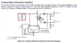
Is this a typo on the DataSheet

or is that referring to the >=47 uf cap from this paragraph

and the designer picked 100uf vs 47uf
And one more quick question.
Am I correct in assuming this 100uf cap would be an electrolytic?
Cheers
This thread has been locked.
If you have a related question, please click the "Ask a related question" button in the top right corner. The newly created question will be automatically linked to this question.
Is this a typo on the DataSheet

or is that referring to the >=47 uf cap from this paragraph

and the designer picked 100uf vs 47uf
And one more quick question.
Am I correct in assuming this 100uf cap would be an electrolytic?
Cheers
Hello John,
The capacitor on the input shall be above 47uF, so we used a 100uF cap there. This will reduce the input voltage ripple. The input capacitor needs to have a certain size for the converter to work properly, but it might need to be increased if the input ripple is still to high for the system. Normally increasing the input capacitor only has positive effects on the system as well as on the converter operation.
You can use an electrolytic capacitor, but I would recommend to add a ceramic one in parallel, e.g. 1uF or 10uF to have a low impedance on the input and get lower ripple. For the converter an electrolytic one is fine.
Best regards,
Brigitte
Hello John,
Yes, the sum of Iload is in this case the current in the positive and negative output. So if your load current is 225mA on both outputs, the value is 450mA.
Even if the value that you calculate is above 3 kohm, please do not use a higher value as 3 kohm.
Best regards,
Brigitte