This thread has been locked.

If you have a related question, please click the "Ask a related question" button in the top right corner. The newly created question will be automatically linked to this question.

TPS53355: Loop stability of TPS53355

Part Number: TPS53355

There are the following problems about the loop stability of TPS53355:

 the input voltage is 12V, the output voltage is 5V, and the RMS value of the actual current is 5.66A,Test point is R2552, the schematic diagram is as follows

1. The phase does not cross zero, please help to assess the risk and whether it has an impact on the loop stability. At the same time, please give suggestions for improvement.

2. The switching frequency is 500KHz, and the crossing frequency is only 2.35k which is low. Is there any hidden danger and risk that needs to be adjusted? Please also give suggestions for improvement.

Thank you

3582.tps53355.pdf     

  • Hi Jimmy,

    The low crossover frequency is not a huge concern for me in this case, but a lower bandwidth can affect transient response. As far as the phase is concerned, it appears that the phase rises above 180 and then the frequency analyzer defaults to the negative half of the phase range. I would expect the phase to crossover here, which may warrant some investigation. 

    With the DCAP topology, we must consider the ESR of the output capacitors, particularly the 2x100uF bulk capacitors in the attached schematic. Following the equivalent ESR calculation we then can refer to section 8.2.2.2 in the datasheet to determine the capacitor and resistor sizes needed for the ripple injection circuit. I would be curious what is the ESR of the bulk capacitors is and can then make a better determination if the ripple injection circuit is implemented in a recommended fashion. 

    I would ultimately defer to load transient response as the primary means of determining stability in this design, but the ESR information may help us better optimize the bode response. Please let me know if you have any further questions or follow up information!

    Sincerely,

    Alec Biesterfeld

  • Hello Alec:

    for the last reply, there are some following questions:

    1. Is there a corresponding curve table or chart corresponding to the D-CAP architecture and the Bode chart?

    2. What is the relationship between RL \CL \CC resistance capacitance and zero pole of gain curve in D-CAP architecture?

    3. What is the relationship between RL \CL \CC resistance capacitance and zero pole of phase curve in D-CAP architecture?

    4. Is it convenient to provide Bode diagram, simulation tool or calculation table of tps53355

    5. What are the main reasons why the phase margin is less than zero? What factors are the general causes of phase margin not crossing zero?

    6. The ESR values on the board are as follows. Please help to review and provide suggestions for power design optimization.

    model 

    vvalue

    ESR

    Frequency point

    number

    PA300LV107M1C

    100uf

    30mohm

    100kHz

    2

    CC1210MKX7R6BB476

    47uf

    2.5mohm

    500khz

    2

    CL21B106KPQNNNE

    10uf

    3.6mohm

    500khz

    1

    CL05B104KA5NNNC

    0.1uf

    70mohm

    500khz

    1

  • Hi Jimmy,

    To answer your questions:

    1. While there is an open-loop transfer function of a DCAP control topology, the output voltage is compared by a comparator as opposed to an error amplifier, which essentially has infinite bandwidth, so the Bode Plot is not necessarily meaningful.

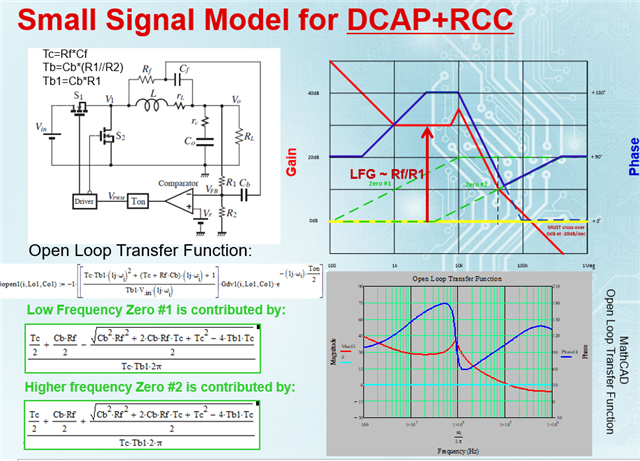
    2/3. The RL/CL/CC contribute to a low frequency and high frequency zero when modeling the open-loop transfer function. The image below details the derivation.

    4. While Bode plots can be convenient, Load Transient stability is a better arbiter of stability when characterizing the performance of the TPS53355 in your design.

    5. I have not calculated your schematic's transfer function, but I would argue that your higher frequency zero is contributing to the rise in the phase curve, which is not crossing over. This is not necessarily important in a DCAP part.

    6. The ESR of the output bulk capacitors acts as a current sensing and summing element in the DCAP topology. Equations 7 and 19 in the datasheet detail the impact ESR has on performance. Based on your schematic, you have sufficient output capacitance and acceptable ESR for stability and jitter performance.