This thread has been locked.

If you have a related question, please click the "Ask a related question" button in the top right corner. The newly created question will be automatically linked to this question.

UCC28780: Control Law Regulation

Part Number: UCC28780
Other Parts Discussed in Thread: UCC28C43, TL431

Hi Team,

I am designing a ACF Flyback Converter using the TI UCC28780 controller. 

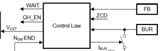
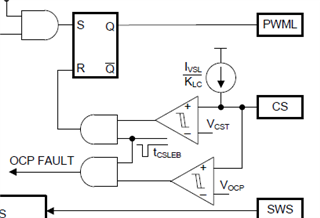
Currently, I am interested in the regulation loop of the controller. I would like to know more about the "control law" box that is inside the controller.

There is no detail in the datasheet and I need to know the transfer function of this box in order to draw the open loop transfer function. (Bode plot)

Could you please help me about this ? 

Moreover, I would like to replace the optocoupler with an isolated digital amplifier ( like ADuM3190 or equivalent). Are there any special precautions to take ?

Thank you for your help.

Regards,

Maxime

  • hello,

    thanks for your interest in ACF controller, the owner of this post is on site support today, will reply you by the end of tomorrow.

  • Hi Maxime,

    The "control law" is confidential for TI that is can not public, in datasheet section 8.2.2.7, there is a chapter detailed explain the loop compensation and provided transfer function(equation 44) ,  pole and zero position. Hope there can help you .

    I think the isolated digital amplifier ADUM3190 can be used with UCC28780 , on primary side , just connect the EAout2 to FB pin of UCC28780 in series a ~20kohm resistor .

    Thanks.

  • Thank you for your answer. It helps me a lot.

    I have a last question about the protection part. 

    In the picture below, we can see the CS voltage is compared to Vcst and if Vcst is above a threshold value (Vcst_opp), the OPP is triggered.

    In the same way, CS voltage is compared to Vocp (1.2V) which is far above from Vcst_opp (600mV) for the OCP. So my question is :

    How and in which case the OCP is triggered ? In my point of view, the OCP will never be triggered because the CS voltage will reach the Vcst_opp first and it will reset the RS flip-flop.

    Thank you for your help.

    Regards,

    Maxime

  • Hello Maxine,

    The OCP threshold may be trigger in the case of a saturating transformer where its inductance drops to essentially the leakage inductance level.

    In this case a high bulk voltage can drive a very high di/dt and the peak current can significantly exceed the usual Vcst_max level during the turn-off delay.  Then OCP will stop switching and run through a 1.5-s restart cycle.

    In non-saturated situations, you are correct, the peak current will be caught by the Vcst_max threshold and should never reach the OCP threshold.

    Regards,Ulrich

  • Hello Ulrich,

    Thank you for your information. This resolved my issue.

    I would like to ask you a last question. As i said above, I try to replace the optocoupleur with an isolated digital amplifier like ADUM3190.

    In fact, this device provides a voltage in output and we need a current for FB Pin ,right ?

    So how can I efficiently change the voltage into a current at the primary side ? 

    Thank you for your help.

    Regards,

    Maxime

  • Hello Maxine,

    I suggest for you to refer to this app-note https://www.ti.com/lit/pdf/sboa233?keyMatch=VOLTAGE%20TO%20CURRENT%20CONVERTER&tisearch=search-technicaldocument which discusses such a voltage to current converter. The design in this App-note needs to be scaled up by a factor of 10, but the principle should be the same. 

    Regards,Ulrich

  • Hello Ulrich,

    Thank you for your quick answer.

    Moreover, for which value of iFB should I design this converter ? iFB depends on the output load so it is variable. 

    Regards,

    Maxime

  • Hi Maxine,

    Please arrange the V-to-I converter such that iFB = 0uA at maximum output current, low-line, and iFB can go at least to 100uA during an output overshoot.  Technically, iFB > 75uA will have no further change of operation than at iFB = 75uA, but it helps to have some margin above 75uA to allow for some variance.  

    Regards,
    Ulrich

  • Hi Ulrich,

    I do not understand why there is no nominal value for iFB depending on the Vout. Most of the time ,like the UCC28C43, a nominal iFB is given in order to inform the controller we select this current for a specific nominal output voltage. If not, how the Controller makes the difference between a 20V output and a 40V ( at the same output power). 

    Thank you for your help.

    Regards,

    Maxime 

  • Hi Maxime,

    The secondary-side regulator (SSR) (such as a TL431 shunt regulator or a voltage error amp plus reference) does the Vout regulation.  The error voltage from the SSR generates an error current through the opto-coupler and this current adjusts the power through put of the flyback. If Vout starts rising too much, the iFB current goes up and the power level is reduced.  If Vout starts sagging too much, iFB goes down and power level is increased to bring Vout up again.

    This is a very common feedback arrangement for many controllers which rely on SSR.  Vout is regulated on the secondary side and iFB is adjusted as needed to increase or decrease power throughput to maintain the regulation as line and load changes.

    Regards,

    Ulrich