This thread has been locked.

If you have a related question, please click the "Ask a related question" button in the top right corner. The newly created question will be automatically linked to this question.

TPS61099: Vbatt voltage dropped when the boost started up

Part Number: TPS61099

Hi

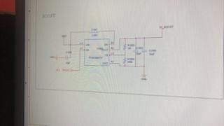
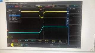
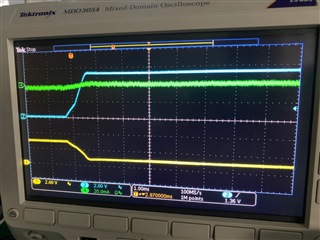
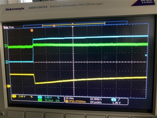
TPS61099 is used in our design for 5V output from the 3V input voltage. LiMn Battery (CR2032) was used for the 3V input. And then we can found the 3V input voltage dropped when the boost started up. This drop can caused our system reboot.
My questions:
1. Please help to check if the drop is expected
2. How about the current when the boost started up?
3. If you have any suggestions on how to fix this issue

BTW, we checked the issue without the loading on TPS61099. And still see the issue.

You can get more from the case CS0537905

https://ticsc.service-now.com/sys_attachment.do?sysparm_referring_url=tear_off&view=true&sys_id=20128e4b1b50f49c602cf715464bcba2

ticsc.service-now.com/sys_attachment.do

  • Hi Jianqiang,

    I tried to search the case "CS0537905" in the e2e but no results. Could you please tell me where I can get the information? BTW, I cannot open your link.

    The TPS61099 has integrated the soft-start mechanism inside, which limits the peak inductor current below 200mA until Vo reaches to 1.6V. You can find so in datasheet description 8.3.4 and waveform Figure.23.

    My best guess is 100mA~200mA current needed by TPS61099 pulled battery voltage drops. You can do so by using a E-load externally and manually add 150mA load to this battery and see what happens.

    -Wenhao 

  • Hi Wenhao,

    Thanks for your information.

    For this issue, the drops also happened without any loading on the output TPS61099. 

    As you know, the Internal impedance is about 100 ohm which is very big. so we want to know the current when boost is powered on.

    Thanks

    Jianqiang Yuan

  • Hi Jianqiang,

    The schematic and waveform you shared is very vague. I cannot see it clearly. But as you may know, TPS61099 has to draw the current from input to charge output capacitor even though there is no load on output side. At the beginning, the device operates at the boundary of Discontinuous Conduction Mode (DCM) and Continuous Conduction Mode (CCM), and the inductor peak current is limited to around 200 mA during this stage. So the average input current is ~100mA. Based on your application, you can also test the average current by test the inductor average current. 

    The impedance of battery is too large to sustain this 100mA charge current.

    -Wenhao

  • Hi Wenhao,

    Thanks for your supports.

    100mA charge current seems be larger for this system It can cause this drop. 

    BTW, Do you have comments or solution for this Power supply solution? 

    Thanks

    Jianqiang Yuan

  • Hi Jianqiang,

     I think there are maybe three ways to help mitigate the issue below, but I need to think about the feasibility.

    1.Increase input caps to sustain this 100mA charge current and prevent battery voltage from drop too deep;

    2.Decrease the current consumption from TPS61099;

    3.Increase the battery voltage;

    I will get back on you before Tuesday. Thanks!

    -Wenhao

  • Hi Wenhao,

    Thanks for your  feedback quickly.

    1. Yes. we tried to increase the caps. The drop voltage level can be decreased too. But the issue didn'tdisappear.

    2. Yes. Please help to check if we can decrease the current from TPS61099. BTW, if you have any other boost for our requirement , please also share to us.

    3. This requirement is from our end customer. they want to use the standard LiMn Battery (CR2032). And now we are discussing with them if they can change it to another one. 

    Thanks

    Jianqiang Yuan

  • Hi Jianqiang,

    How are you controling the EN? I am wondering if we can delay EN and only start up the device after Vin has been fully established. 

    -Wenhao

  • Hi Wenhao,

    We are using one GPIO to control the TPS61099.  We can delay the EN. We tried the solution before, but still see the issue when we enable the EN pin.

    Thanks

    Jianqiang Yuan

  • Hi Jiangqiang,

    I tested the start-up current for TPS610995 which is a fixed voltage version of TPS61099.

    As you can see below, Ch2 is Vo, Ch4 is Inductor current. I used EN to ramp up the VO after VIN has been fully established. TPS61099 first ramps Vo with 100mA charge. After that, when the output voltage is charged above approximately 1.6 V, the device starts the hysteretic current mode operation. The current limit threshold is gradually increasing to 0.7× ILIM within 500 μs. So you can see here inductor current actually increased. This forced input current larger than 100mA after Vin>1.6V, which makes start-up more difficult with CR2032. The peak inductor current increases with current limit threshold gradually increases.

    Theoretically, adding the input capacitor can actually works depends on how much capacitance you add. Suppose in the worst case there is no current from battery, the TPS61099 has to draw all the charge from CIN. If CIN is large enough to support VOUT to rise, then the final input voltage is VIN-COUT*VOUT/CIN. If this voltage is larger than UVLO, then the device is still alive.

    Assume VIN=3.0V, VOUT=5V, COUT=20uF, to ensure the input voltage not exceed 0.5V (TPS61099's UVLO), the Cin should be larger than 40uF+some margin. I assume 20% margin here so 48uF can be used here.

    Decrease current assumption cannot be used here. Even though I can extend the soft start up time after Vo rises to 1.6V (see SLVA307B), there is maybe no way we can decrease the 100mA charge when VOUT<1.6V.

    I will check if there is any other DCDC which can meet your requirement. Please allow me two days.

    -Wenhao

  • Hi Wenhao,

    Thanks for your great supports.

    Thanks

    Jianqiang Yuan

  • Hi Jianqiang,

    I would recommend you to add more capacitance on input side. I tested the start-up with 12-ohm series resistor between input source. This actively limits current from input source when start up. See the waveform below:

    Ch1 (yellow) is VIN, Ch2 (Blue) is VOUT, Ch4(green) is current from input source. I have add additional 2*0805/47uF/10V/X5R caps on top of EVM's. In total there are 104uF capacitor. the effective capacitance considering DC bias effect could be about 50% of original value, which is 52uF.

    From this waveform, we can see after EN, TPS61099 draw all charge from input capacitor, there are only about 5mA current sourcing from input source. I think this configuration can simulate the sourcing capability of CR2032. TPS61099 finally ramps up the Vo without shutdown. VIN drops to about 0.8V, but it is still above UVLO threshold.

    Zoom out the waveform, we can see input source charges input caps slowly with almost 5mA constant current.

    I think adding input capacitance here should solve your problems. You can add more capacitance if you do not want VIN drops so low.