TPS40303 team,
A customer designed a board with TPS40303 to support up to 21A load. The Overcurrent isn't expected to be a factor since it is programmed at about 55 to 60A with R = 15.4kOhm.
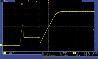
They tested first with current well below 21A, probably 5A, and all was fine. They increased the current to about 10A, and it ran fine for 2 to 3 minutes then shut off. Since then, the regulator can't bring the rail back up. See attached plots of the SS pin on the failed board.
My suspicion is that the high side FET was damaged somehow, but before they go resoldering, does this type of pattern mean anything to you? You'll see the HDRV scope capture below as well.
Thanks,
Darren
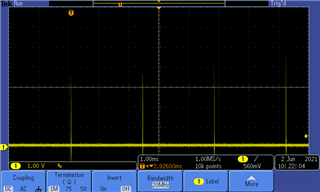
SS on failing board
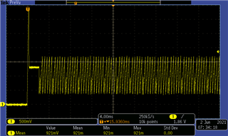
SS on failing board
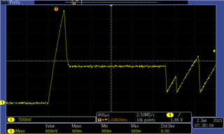
SS on failing board
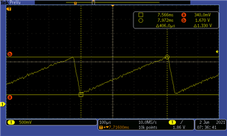
SS on Good board (before failure)
HDRV pin on failing board with no load.