This thread has been locked.

If you have a related question, please click the "Ask a related question" button in the top right corner. The newly created question will be automatically linked to this question.

LM5155EVM-SEPIC: The EVM board has ringing

Part Number: LM5155EVM-SEPIC
Other Parts Discussed in Thread: LM5155

Hi,

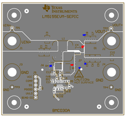
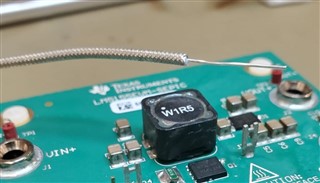
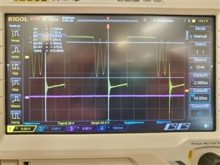
I've loaded the LM5155EVM-SEPIC with 10 ohm load. Vin 17v. Switching frequency 2.14MHz

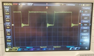
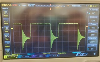
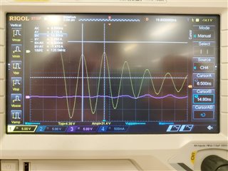
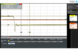
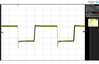
I'm observing very large ringing on:

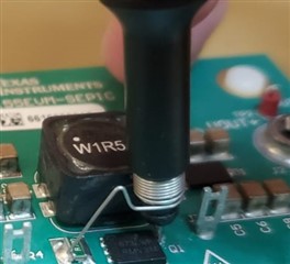
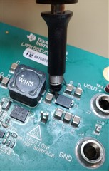
Output diode's anode
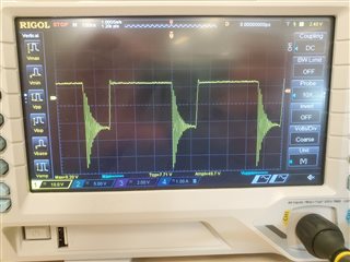
FET's drain

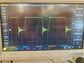
The frequency of the ringing is the same on both nodes

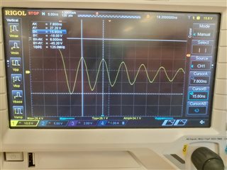
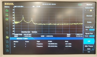
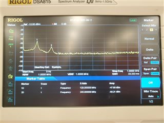
That results in wide spectral noise

I've tried to use snubbers across the FET and/or across the diode, made the sepic capacitor C4 larger but no change in the ringing.

Please advise how to eliminate this ringing.

  • Hello Arkady,

    Thank you for using our device and checking out the EVM.

    For observing the noise on these nodes, I would recommend to use an active probe with very short connections. Could you please re-check the ringing with very short GND connection of the probe to the appropriate ground close to the components?

    Best regards,
    Brigitte

  • Hi Brigitte,

    I've repeated the measurements with short ground and made again spectrum measurement when nothing connected to the EVM's ground except the input voltage. Vin and Vout leads are firmly soldered to the pcb.

    The Vdrain ringing is clearly smaller when measured with short ground (R4 ground), when measured with respect to J7 ground Vdrain ringing is higher.


    Diode's anode voltage made with short ground stayed as high as before. Measuring anode's voltage once with respect to C8 ground and once with respect to C5 ground made no difference.

    The spectral measurement is radiated was made by placing an exposed semi rigid wire above the circuit. On the spectrum you can clearly see the same ringing frequency 125Mhz and it's second harmonic 250MHz.

    Regards,

    Arkady

  • Hi Arkady,

    i would like to check this also on the bench and discuss with one of our RF expert. 

    Please give me a few days for that - i will try to give you more details mid of next week.

    Best regards,

     Stefan

  • Hi Arkady,

    i did some measurements in the lab and can see a similar behavior.
    As the EVM are designed by evaluating the devices doing measurements and also allowing to adjust the circuit for end application specific requirements the layout can not always be made perfect, esp. considering RF specific requirements.

    The is a TI Reference design which has been optimized for HF, may you would like to review that one and can try to adopt this to your requirement:

    PMP30805 Tiny automotive SEPIC reference design | TI.com

    Can might also setup your design to run in DCM mode this issues would be highly reduced or even completely removed as the Energy in Qrr would be completely removed in each cycle.


    Best regards,

     Stefan

  • Hi Stefan,

    I've configured the EVM to DCM mode, it required to lower the frequency to 418MHz, this probably will require to use larger inductor. Still, in DCM mode I can observe the same 120MHz ringing coming from output diode's anode. The ringing is shorter but with high amplitude. See pictures.

    PMP30805 is a very nice design and I believe it's quiet, it has snubbers on the FET and the output diode, SEPIC capacitor is also significantly higher. Unfortunately I cannot use this design and it's components as a reference because I need to evaluate the LM5155 with at least 1.5A output current. As I mentioned before I've tried to put snubbers on the FET and the diode and changed the value of the SEPIC capacitor on the EVM but with no success at all. I need to evaluate the LM5155 in sepic mode with 1.5A output current with no violent ringing before I decide to use it in my design and start with the PCB layout. Please advise how the LM5155 EVM can be fixed to lower the ringing.

  • Hello Arkady,

    Have a look at this information on snubber design:

    https://e2e.ti.com/blogs_/b/powerhouse/posts/calculate-an-r-c-snubber-in-seven-steps

    https://ti.com/lit/slup100

    You can reduce the ringing as well by slowing down the turn on and off of the MOSFET, e.g. by adding a gate resistor.

    Another possibility is using a different Schottky diode or maybe you find a fast recovery diode. Both might reduce the ringing.

    But as ringing is highly dependent on parasitics, it will be difficult to predict the ringing on your board by optimizing the EVM.

    In general I recommend adding a switch node snubber as well as a gate resistor and in addition some high frequency caps on VIN and VOUT extremely small ones and extremely close to the power stage which normally filter the ringing somewhat. The values for all these components need to be optimized on the final layout.

    Best regards,
    Brigitte

  • Hi Arkady,

    I haven’t heard from you for some days, so I’m assuming you were able to resolve your issue. If this is the case, please click the "This did resolve my issue" button. 

    If the issue still exist please describe the current status of your issue and any additional details you may have to assist us in helping to solve your issues.

    Regards,

     Stefan

  • Hi Stefan,

    The only thing I was able to do to improve the  EVM performance is to add 40ohm gate resistor (smaller values of 1, 2 , 5, 10, 20 ohm didn't really help), this almost completely eliminated the ringing but on the other hand it made the on/off time much longer and the fet got very hot as well as the LM5155. I've tried to use a diode in parallel to the gate resistor to speed up the off time but that didn't improve the overheating. Adding inductance instead of Rg also didn't help the overheating. I'm back using 0ohm Rg so I can continue to operate the EVM.

    As for the snubbers, I've already tried it on FET and the output diode with no success - they changed nothing.

    Meanwhile my issue is not resolved as I'm at the same point as I was at the beginning,

  • Hi Arkady,

    when following the description (mentioned above : https://e2e.ti.com/blogs_/b/powerhouse/posts/calculate-an-r-c-snubber-in-seven-steps) on how to implement a snubber on a Rectifier, i could bring down the oscillation immediately to a very low level 


    adding a 5.6 Ohm Resistor into the Gate of the FET further reduces the negative spike on.

    So the main part of the oscillation in the Rectifier Anode has already been damped. Of course this needs to go on cost of the efficiency.

    I am not sure on the expectation you have about the near field probe and for what purpose you have make this measurement. This antenna will pick up all the disturbance around the SMPS but this are not all mandatory in issue for EMI or CISPR measurements. Esp. for the  frequencies around 130 MHz you would need an Antenna length of ~ 30cm to get it radiated into the far field.

    For conducted disturbances the next step would be to optimize the layout.

    Best regards,

     Stefan

  • Hi Stefan,

    I've recalculated the snubber for the output diode and managed to lower the ringing to the same level as in your screenshots. 

    As for radiated measurements I totally agree with you.

    Thanks a lot, that was very helpful.

    Regards,

    Arkady