This thread has been locked.

If you have a related question, please click the "Ask a related question" button in the top right corner. The newly created question will be automatically linked to this question.

LM51551: Used in a boost converter, it continuously hiccups

Part Number: LM51551
Other Parts Discussed in Thread: LM5155, LM51561H

Hello,

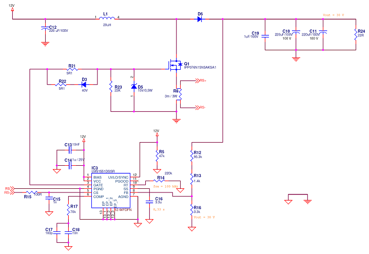
We have designed a Boost converter based on the LM51551 controller. The original design has 50-65 V as input, and 70 V as output, but to test the board we are feeding the input with 12 V and the output is set to 30 V. The switching frequency is 100 kHz. The problem is the controller is continously entering into the hiccup mode; we have tested without load and with several small loads, such as a 22-ohm resistor, and the performance is the same in every case.

Since we did not manage to find the problem, we have made some changes in the testing board to simplify and to get a design as close as possible to the reference design of the datasheets. This is what is currently mounted:

Boost schematics

The last change we have done is removing the R15 resistor and shortcircuiting to ground the CS input by changing the C15 capacitor by a 0 ohms resistor. By means of this, overload should not occur and therefore it should prevent entering into the hiccup mode. However, the controller still hiccups.

We know it hiccups by checking the voltage in the SS pin. This is a picture of it:

Soft Start hiccup

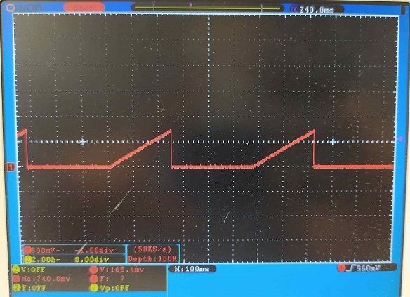
The time until the next start is over 325 ms, that is, 32768 cycles at 100 kHz.

We have mounted two boards and both have the same performance, so it seems a design problem (schematics or PCB).

Any idea or clue to solve this problem will be greatly welcome.

Thanks in advance.

Javier

  • Hello Javier,

    The connection of the COMP components is not as it should be. Please remove C17 and try again. C17 should be parallel to R17 and C18 and not just C17. I expect that this creates instability causing overvoltage on the output.

    If this does not help, please place C17 across R17 and C18. You can in addition use the quick start calculator to be sure that the values are correct.

    Please measure for all tests VIN, VOUT, switch node. COMP voltage, CS voltage (after remounting the right components.

    Best regards,
    Brigitte

  • Thank you Brigitte for your fast response. I cannot  verify it today, I will do it on Monday and I will let you know.

    Best regards,

    Javier

  • Hi Javier,

    have not seen an update from you - have you already been able to finish the test.

    If your issue is solved it would be great of you can close the thread and click the resolved button.

    Best regards,

     Stefan

  • Hi Stefan,

    We have been testing so far, with no success. I was going to take some photos of the scope with some signals but unfortunately the unique operative board we had has just blown (I supplied the controller with 62 V by mistake). Brigitte was right about C17, it should be placed across R17 and C18. However, in that wrong place it does not do any harm since it is in parallel with C18 which is much higher. Anyway, we removed it, and we also replaced R17 by a 9.1 kohm-resistor. I am not sure now (just thought about it) if C17 is necessary; I mean, I thought it was just the second pole (higher frequency) capacitor, as it is in a common type II compensator with operational amplifiers, but I don't know if it has the same function with a transconductance amplifier, as in this case.

    After this change, we checked the signal voltages and they looked correct. The converter managed to boost the input voltage from 12 V to 12.8 V, thanks to the short time the controller worked, before restarting due to the hiccup.

    The gate signal is bunches of short pulses of 200 ns (during the time the controller works), causing that small boost. The CS voltage is also bunches of pulses with about 0.3 V peak voltage. It should not cause hiccup, should it?

    We are designing a new board replacing the LM51551 by a LM51561H that has a larger and easier to handle package (we are manually soldering the components in this prototype phase). We may also mount a board with a LM5155 (without hiccup mode) to see how it performs. I will write again when we test new things.

    Best regards,
    Javier