Hello,
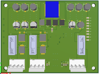
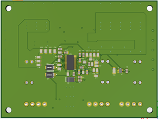
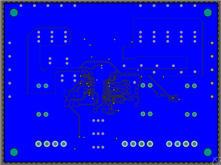
I am working with the LM34936QPWPTQ1 IC following a WEBENCH example for a 12-36V input Buck/Boost converter with 28VDC/8A output. I am currently testing a board design that I made and am not getting the desired output voltage at no load conditions and when even a small current is drawn via an adjustable load the output goes to 0V. I am providing 20V using a power supply and measuring the output voltage and current with the adjustable load.
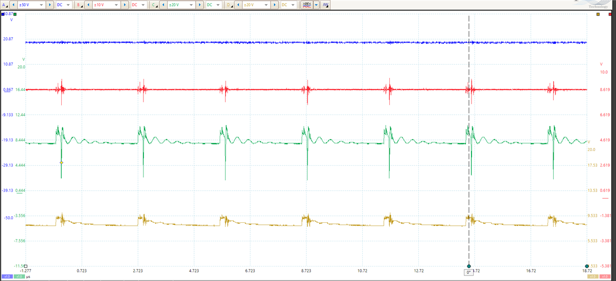
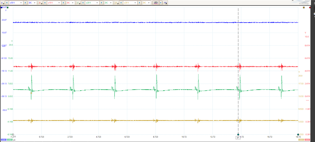
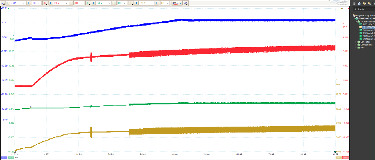
I will include the voltages and waveforms I am seeing on the pins:
1 EN/UVLO: 2.251V
2 VIN: 19.541V
3 VISNS: 20.37V
4 MODE: 2.27V
5 DITH: 408mV
6 RT: 1.59V
7 SLOPE: 420mV
8 SS: 1.58V
9 COMP: 3.6V
10 AGND: 430mV
11 FB: 632mV
12 VOSNS: 8.98V
13 ISNS(-): 413mV
14 ISNS(+): 413mV
15 CSG: 425mV
16 CS: 1.23V
17 PGOOD: 478mV
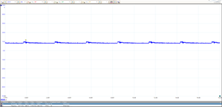
18 SW2 (Average 8.59V)
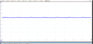
19 HDRV2 (Average 8.3V)
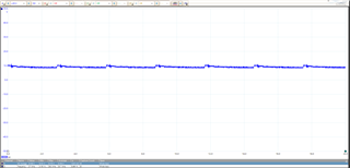
20 BOOT2 (Average 9.16V)
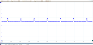
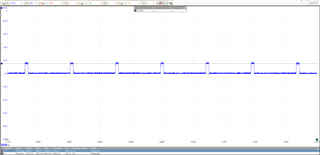
21 LDRV2 (7.7V pulses 342kHz)
22 PGND: 403mV
23 VCC: 7.72V
24 BIAS: 440mV
25 LDRV1 (7.7V pulses 342kHz)
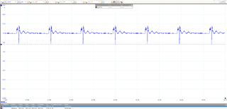
26 BOOT1 (12V to 4V pulses 342kHz)
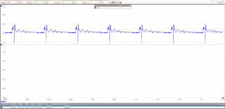
27 HDRV1 (12V to 1.4V pulses 342kHz)
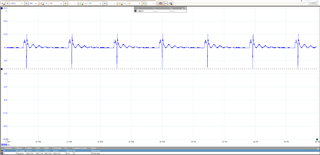
28 SW1 (11.3 to 3.2V pulses 342kHz)
I'd greatly appreciate any help in getting this to work! These waveforms were referenced to the input GND. Please let me know if anything else would be helpful in diagnosing this problem.