This thread has been locked.

If you have a related question, please click the "Ask a related question" button in the top right corner. The newly created question will be automatically linked to this question.

BQ24650: Battery detect not working, STAT2 always high whether battery connected or not

Part Number: BQ24650

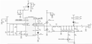
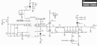
I have posted previously in this forum regarding this same part, but I've since respun these boards and would prefer to start fresh with the problems I am currently having.  On this newest board (schematic below), the first problem I am having is that when the battery (lead-acid) is unplugged, STAT2 is high and STAT1 is low.  Vbatt stays at ~5V.  I have a different design with the same circuit that I believe acts appropriately (Vbatt with the battery disconnected measures ~14.4V and both STAT1 and STAT2 are high).  

The second issue is that the battery never indicates fully charged when the battery is plugged in.  STAT2 continues to stay high, STAT1 is low.  The battery does seem like it is in the float charge state--Vbatt fluctuates between ~14.3V and ~13.5V (I can also hear it charging and discharging--another concern).

The schematic for the board in question is the first picture below, the other design is the second picture. What could I be missing?


  • Additional info:  My Vfb is only making it to about 1.99V--could this be the problem?  Is there a struggle between Vreg and Vfb?

  • Hello,

    Are you sure the component values are all the same, specifically the FB resistors? Can you desolder them and measure them?

    What is the purpose of Q5? If you know you battery regulation is 14.4 V, you set the FB calculation with the upper and lower resistor to achieve this. No need to use a FET.

    Second, STAT1 and STAT2 are open drain outputs. This means that they are driven low when turned on and floating when turned off. Your schematics don't pull up STAT1 and STAT2 to a pullup rail, so anytime its off the voltage is floating and could not be shown properly.

    As for the noise, please check to make sure the impedance to the battery is as small as possible. Can you probe the output with an oscilloscope? If you see a triangular waveform with the frequency in the audible nose band the impedance is the problem. The charger regulates the voltage at the SRN pin. When it terminates however, the voltage at the battery may be less. If it is less than the recharge threshold the charger will start charging again. This will happen on repeat and can make noise if the frequency is audible. To prevent this reduce the impedance to the battery.

    Thanks,

    Mike Emanuel

    Please click "Resolved" if this answered your question.

  • I am reasonably sure the resistors are correct--if I have to, I will desolder them, but I'd prefer not to.  The measured voltages agree with what I have calculated.  

    Q5 was added to float charge the lead-acid battery per SLVA437A.  

    STAT1 and STAT2 do have pullups--that portion of the schematic is shown below.

    I'm not sure I could make the impedance any smaller--the circuitry is all very localized on the board and the only components that are in line are what you see on the schematic--how low are we talking?  

    What oscope captures could I provide that will supply more info?

  • Hello,

    As for the differences in the schematics I found one. The supply for MPPSET is "+12VPS" for one schematic and "Vsen" for the other one. Are the voltages here different?

    Can you please capture a waveform of the input voltage, PH voltage, output voltage, and output current? Please observe the frequency of the recharge if possible?

    Where is the output diode going to? If that is a load, you could be discharging the output and recharging it in just the audible frequency range. Especially because your output is 14.4 V and the 12 V rail in question is more than a diode drop away.

    Thanks,

    Mike Emanuel

    Please click "Resolved" if this answered your question.

  • +12VS is from a 12V power supply and Vsen is from 2 diode ORed +12V power supplies as shown in the first image below. The diode ORed supply (Vsen) is slightly lower (schottky drop) and is on the "working board."  

    Images below.  Order is Vcc (inout voltage), PH voltage, PH voltage on working board, Vbatt (output voltage), zoomed in Vbatt and output current (best I could do is a math function on my oscope across the sensing resistor).

    In regards to the load, this diode goes to a FET that only turns on when the power supply voltage drops below a set value--I measured the gate of that FET and it's off, so no load.

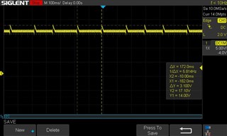
       These peaks occur when the battery is charging.  I checked the other design and the same thing happens, but stops when the charging is complete.
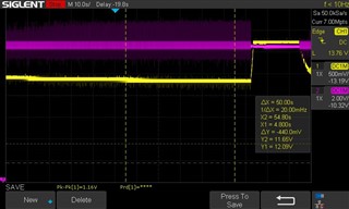
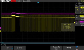
      PH pin

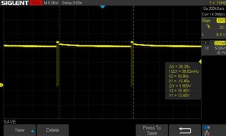
      PH pin of working board
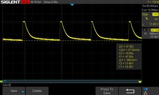
      Vbatt

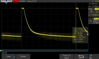
      Zoomed in Vbatt (clicking noise is happening when the spikes are present)
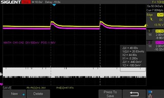
      

  • Hello,

    For the different supply voltages, can you please use a multimeter to measure the different supplies and confirm the voltage is 12 V?

    Can you please zoom in on the battery voltage ringing and see if it has the same frequency as the input voltage ringing?

    Last, can you try increasing the input voltage to the converter to say 18 V instead of the 15 V? This is a buck converter and due to the layout more headroom from the input voltage to the output voltage may be needed.

    Thanks,

    Mike Emanuel

    Please click "Resolved" if this answered your question.

  • +12VPS = 12.00V, Vsen = 11.88V

    I have no means to increase the input voltage--and the other board design is working fine with this same input.  Why would this one be different?

    Also, why would PH be going crazy as I show in my last post?

    Pictures below: Yellow is Vbatt, Pink is VCC

      Zoomed out

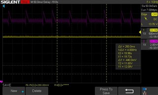
      zoomed in a bit more
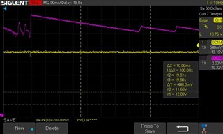
      zoomed in

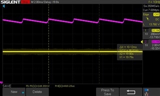
      better resolution on Vbatt

  • Hello,

    We do not recommend running buck converters on full duty cycle. With efficiency losses and parasitics, you could be trying to operate the buck converter with a 15 V input and 14.4 V input at maximum duty cycle. That is why I recommended to increase the input voltage.

    Can you please take a waveform of PH on the working board with the input voltage at the same time? I want to see if the triangular noise on the input is there.

    Can you investigate why you have a triangular waveform on the input?

    Thanks,

    Mike Emanuel

  • Are you referring to the internal buck converter of the BQ24650?

  • The actual converter of the BQ24650 is external. It involves the high side and the low side FETs, the inductor, the output capacitors, and the input capacitors. The BQ24650 provides the gate drive signals and compensation. The battery charger is a buck converter, in your case with a 15 V input and roughly maximum 14.5 output. If your design works perfectly through the charge cycle but has issues operating at fully duty cycle I would try to increase the input voltage and see the effect.

    Thanks,

    Mike Emanuel

    Please click "Resolved" if this answered your question.

  • I am going to replace a resistor on the board to increase the supply voltage and let you know how that goes.  Hopefully I will get this done tomorrow, but if not, then Saturday.

  • It looks like increasing the supply to 20VDC worked--thank you very much for your help!