This thread has been locked.

If you have a related question, please click the "Ask a related question" button in the top right corner. The newly created question will be automatically linked to this question.

UCC25800EVM-1: UCC25800-Q1

Part Number: UCC25800EVM-1
Other Parts Discussed in Thread: TL431

Dear TI team,

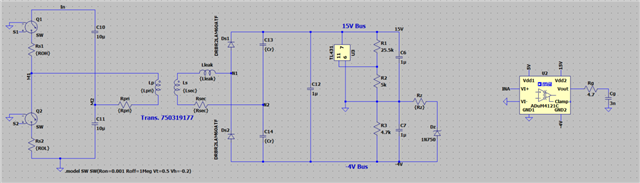
Below is the schematic for regulating both negative and positive rails of isolated bias supply from TI reference design "Using the UCC25800EVM-037 2-W LLC Converter for
Traction Inverter Driver Bias Power Supplies". This schematic used two TL431s to regulate +18V and -5V.

Do you have simulation model file that can send me? I have tried to use two TL431s to regulate +15V and -4V for my applications, but only regulation of +15V works. -4V regulation always loses control in my LTspice simulation.

Thanks and regards,

  • Hi,

    The simplis model can be obtained from this link www.ti.com/.../slum781.

    To make your -4V into regulation on the circuit similar to UCC25800EVM-037, the load on -4V should be similar to +15V, but -4V load current should also be lower than the current on 15V. +15V and -4V load currents are affecting each other.

    The EVM test shows, +18V load current needs about 1mA higher than -5V current in order to make good regulation on both output voltages. If not 1mA, then the regulation gets different and depending on your requirement to see how much current difference can be.

  • Hi,

    I am not able to download the file you attached, could you check that? Do you have LTSPICE/SPICE model or just SIMPLIS model?

    My circuit model is below. I just removed the lower TL431 since it does not work previously. 

    Why +18V load current need to be 1mA higher than -1mA load current? Should it all depend on the gate driver circuit? I use an actually gate driver circuit to charge and discharge a gate capacitor like below.

    Thank you so much for your opinion.

  • Hi,

    We only have simplis model. I checked and downloaded before asked you to download  so you may try to download it in a later time if you cannot make download.

    Basically, 18V and -5V are in series connection. In a certain load current range each regulation is ok to maintain. But if the current has too much difference then the regulation especially the -5V regulation cannot be maintained to be acceptable. For example, if 18V has only 10mA load, while you want to get 30mA from -5V, the additional 20mA cannot get from the series connection with 18V, while there is no additional path in work, to the -5V regulation would become bad.

    Another is if 18V with 80mA, note that 80mA would have to flow through the 18V load and also need to flow through -5V. If you have -5V with 0mA, then the TL431 with -5V has to sink 80mA - which if is not designed that way, then -5V regulation will become bad (increase to -6V or even higher).

    There is no requirement of 1mA. The 1mA is based on my test which can give the best regulation for both 18V and -5V. I mentioned, how much current difference between 18V and -5V depends on your voltage regulation, but also on the design you are testing.

    It looks your circuit is similar to the EVM. So the analysis above should be applicable to yours.

  • Hi Hong Huang,

    Thank you very much for your feedback. 

    When you measured the efficiency of the circuit in the Evaluation board, did you use a resistor as load?

    I still don't understand your argument. The load of the isolated bias supply is gate driver circuit, correct? And the load will depend on switching frequency as well as the Mosfet we drive. How can we have a control on load current as in your explanation?

    Thanks a lot!

  • Hi,

    Using a constant load like a resistor or a constant current load to measure the efficiency of a converter is a commonly used approach to compare efficiency between converters.

    A converter is rarely used for constant load. But to make comparison and to check if a converter meeting specs or not, it is common to use a fixed loading range to make comparison.

    When you have different fsw and MOSFETs, usually you convert these into a load range for converter performance test. You can also add transient test specs to check the transient performance. This is a commonly used approach. After that, you can test the converter on your real situation. So your load range and your transient specs need to work out to cover your real load situation. 

  • Hi,

    What do you mean by adding the transient test specs? Do you mean to estimate the load range (power) during transient, and convert it to a pure resistor load?

    Thanks!

  • Hi,

    A transient load test is some like to test load current step change then to check how much Vout deviation can be. In this case, you  can use two resistors, with two different values, so in a test, you can use a switch to connect one resistor to the converter, or connect two resistor to the converter, the current will be change from one level to another, then you check the Vout during the resistor change, to see Vout deviation is good and acceptable.

    If you have an e-load that can do this for you, you can use such a load, and set up two different current level, and set up the e-load to switch current up and down, then you can observe the converter Vout to see if acceptable.