


Hi team,
I got a question from customer.
When using bq25886 to charge two lithium batteries, we encountered the following problems:
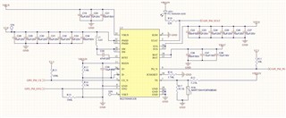
The 1A charging current (external adapter) is only 290ma, and it is useless to adjust the ground resistance of ichgset. The circuit diagram is as follows:
remarks:
- 5v5a DC power supply is used. The battery power is very low, and the open circuit voltage of the battery is only 7V.
- When charging, the voltage of regn is 5V (normal), 2-pin stat and 9-pin PG are normal (both pins are to the ground, and the indicator light is always on). The charging current is abnormal.
- R13 is not welded (because 3-pin is low enable), 3-pin CE and 5-pin OTG have no input signal (3-pin flying wire grounding has also been tried, the situation is the same).
- Short circuit on 24 pin and 1-pin circuit boards, and then try to connect 1.8V, 5V, grounded or suspended according to the circuit diagram.
- If the charger is connected first and then the battery is connected, the adapter terminal current can reach 770ma.
- 15, 16 pin sys voltage: connected to the battery (whether connected to the adapter or not) is equal to the battery voltage, not connected to the battery, only connected to the adapter is 6.3V.
- The "V5.0" connected by pins 21 and 22 in the circuit diagram is not connected with any circuit.
- The 6-pin Vset is suspended and the 8-pin Ilim is grounded( It is allowed on chip data)
- The capacitors and inductors on the PCB are arranged in strict accordance with the requirements of the device data. The attribute values of each device have been checked repeatedly, and the accuracy of the selected devices is 1%.
Thank you very much for your help.
Best regards,
