This thread has been locked.

If you have a related question, please click the "Ask a related question" button in the top right corner. The newly created question will be automatically linked to this question.

LM2611: High-Duty Compensation Calculation

Part Number: LM2611

Hi,

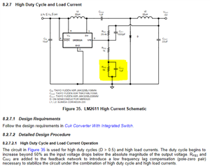
I am designing a converter around the LM2611 to produce a -12V rail from a 3-5V input. This would give a duty cycle of ~73%, which per the datasheet requires the addition of an extra compensating pole-zero pair in the feedback loop (pictured, from p. 19 of the datasheet).

How are the values for these components calculated? I plan to use 22uH inductors and a 1uH Ccuk capacitor, with Rfb2=5k and Rfb1=44.2k.

  • Hi Matthew,

    sorry but we don't have a tool to calculate the value of these components. as the device had been released for long time, i also can't find the internal compensation value.

    i would suggest you applying an EVM and try bench test to find a value that good stability during load transient.