This thread has been locked.

If you have a related question, please click the "Ask a related question" button in the top right corner. The newly created question will be automatically linked to this question.

TIDM-ULTRASONIC-FLOW-TDC: Interfacing with MSP-FET and Computer

Part Number: TIDM-ULTRASONIC-WATER-FLOW-MEASUREMENT
Other Parts Discussed in Thread: MSP-FET

Hello,

I am trying to interface the TIDM-ULTRASONIC_FLOW_TDC to my laptop using the MSPFET and the TDC1000-TDC7200 GUI. However when I plug the MSPFET into the board after connecting the appropriate jumpers I get the error "MSP430: Error initializing emulator: The voltage 1524 value is not correct/allowed for the USB FET". How do I go about fixing this and interfacing the board with the PC? I also have an EZ-FET if that is more applicable than the MSP-FET.

I have attempted to use a multimeter to make sure everything is connected, however due to every store being out of stock, I was unable to obtain the Buck converter for U3. This means that I connect 3.3V from the MSPFET directly to the output pin from the converter. 

  • Part Number: TIDM-ULTRASONIC-WATER-FLOW-MEASUREMENT

    Hello,

    I am trying to interface the TIDM-ULTRASONIC_FLOW_TDC to my laptop using the MSPFET and the TDC1000-TDC7200 GUI. However when I plug the MSPFET into the board after connecting the appropriate jumpers I get the error "MSP430: Error initializing emulator: The voltage 1524 value is not correct/allowed for the USB FET". How do I go about fixing this and interfacing the board with the PC? I also have an EZ-FET if that is more applicable than the MSP-FET.

    I have attempted to use a multimeter to make sure everything is connected, however due to every store being out of stock, I was unable to obtain the Buck converter for U3. This means that I connect 3.3V from the MSPFET directly to the output pin from the converter.

  • Hello Matt,

    Are you seeing the 3.3V at Vcc on the MSP430 device?  Do you have JP6 connected?  

    You could also use the eZ-FET connected to the J1 header.  You will need to connect TST, RST, Vcc, GND.

  • Hi Eddie,

    Thank you for the response. I am seeing 3.3V at Vcc for the device. However, As I do not have the buck converter, I am attempting to just wire the 3.3V output of the converter to the 3.3V input. When I do this, the Vcc pin drops to 1.7V. I have attempted to disable everything in the software that would use the converter select pins so that it just uses the 3.3V from the MSP FET, but I have not been successful.

    I have also tried using the eZ-FET with the exact same issues. I have JP1, JP6 and pin and 2 of J5 connected. I looked at the schematic and saw that theoutput of the converter, which we would expect to be 3.3V, is connected to e bottom pin of JP5, so I also have that connected to the 3,3V Vcc. However, when i connecte that pin Vcc drops to 1.7V.

  • Ok.  Something is causing your voltage to get pulled low.  Can you provide diagram of how you have it wired.  Maybe that will help spike something out.

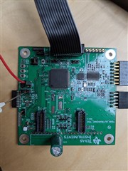
  • I am sourcing power from the MSP-FET plugged into my USB port on my computer. I have connected jumper 1, jumper 6, pins 1&2 of J4 and then to try and bypass the buck converter, I have connected the bottom pin of JP5 to the jumper on J4. I looked at the altium PCB files and saw that the output pin 5 from the buck converter is connected to the same net as the bottom pin of JP5 so I thought I would be able to provide power to that net this way. When reading the data sheet for the converter though I noticed that it says some pins need to be terminated and the voltage select pin needs to be set. Could that be an issue with this method? I have tried to adjust the source code with no luck. 

    Thank you!