This thread has been locked.

If you have a related question, please click the "Ask a related question" button in the top right corner. The newly created question will be automatically linked to this question.

TPS549D22: TPS549D22

Part Number: TPS549D22

Hi Team,

Customer wants to change the voltage setting in the internal NVM.

It will be difficult for my customer to turn the output off while device is operating to use STORE_DEFAULT_ALL, as they would end up violating their power startup sequencing.

We configured TPS549D22 default output to 0.975V.

As soon as we update output voltage change or frequency change from FPGA via PMBus interface will it take some time to update the new changes we done? if yes, what is the time interval?

or is it requires power on reset to update new changes?

If we change switching frequency or ss configuration do we need to re-boot the IC or not

Regard's

Raghavendra M

  • Hi Raghavendra,

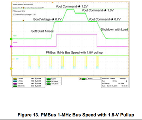
    The TPS549D22 supports dynamic voltage adjustment via the VOUT_COMMAND. Figure 13 in the datasheet demonstrates this behavior. It will take some time to update the output voltage. For example, figure 13 indicates that it takes roughly 3ms to change the voltage from 0.7V to 1.2V.

    To change the soft-start time, you would have to change the pinstrap resistance and reboot the IC. There is a bit in the MFR_SPECIFIC_02 register that will allow the customer to toggle between external and internal soft-start with the internal soft-start setting being a default of 1ms. For this setting to take effect, it must be followed on by a STORE_DEFAULT_ALL command and a power cycle of the device.

    Switching frequency can be adjusted without re-booting the IC.

    Regards,

    Alec Biesterfeld

  • Hello Alec,

    Thanks for the quick response, 


    1. As your mentioned 3ms duration to settledown the output voltage. During this transition time(3ms), we understood that the load will not be disturbed/disconnected?
    From the graph we understood that there is no rampdown in Vout, when VOUT_COMMAND is applied.

    2. Pgood delay can be change dynamically? reboot is must required confirm?

    3. We configured TPS549D22 Vout = 0.975V, what is the Vout tolerance(wrt to IC Vout), . What will be the max. and min. output voltage during operation.

    Regard's

    Raghavendra M

  • Hi Raghavendra, 

    To answer your questions:

    1. The load does not need to be disconnected when the output voltage is changes. 

    2. Yes, changing xD1 will allow for dynamic adjustment of the PGOOD delay. The device will need a store command for the setting to be applied following a reboot, but a full device reboot is not necessary. 

    3. Given the resolution of the VOUT COMMAND register, I would expect the tolerance of your output voltage to be +/- 2mV. With a load applied, you may expect +/- 0.5% tolerance. This means that the output should be between 0.973V and 0.977V under nominal conditions. Across the full load rating of the device, I would expect the output to remain between 0.971V and 0.979V.

    Sincerely,

    Alec Biesterfeld

  • Hello Alec,

    Thanks for the response,

    We have few more clarification required on this from different team members in our team. IS this possible to have meeting with your technical team today before 3:00 pm. Please comments on this.

    Regard's

    Raghavendra M

  • Hello Alec,

    We are planning to implement few parameters in our design and please confirm what are the assumption we made are correct if not please correct. 

    I read in few FAQ's that pre-programming the TI IC before they ship. How to contact TI for this and let me know if any terms and conditions for pre-programming the TI IC for ex.: MOQ.

    Parameter PMB Interface command Description IC reboot required Impact on power up and down sequence HW change requirement Optional Hardware setting  ELF change requirement Conclusion (Can be included in Design or not)
    Output Voltage VOUT_COMMAND Output voltage setpoint. DAC resolution is  1.9531mV and
    range is ~0.6V to ~1.200V
    NO 3ms delay impact for the new configured output Nothing R199 should be Depopulate for 0.975V & Populate if 0.95V Vout  Need to write PMBUS code for the same Electrical performance is guaranteed for the change. ELF implementation is must for future
    Switching frequency MFR_SPECIFIC_03 Program Fsw and control
    mode, Read RC ramp
    NO Nothing Nothing   Electrical performance is guaranteed for the change. ELF implementation is must for future
    Soft-start-time MFR_SPECIFIC_02 Read SST, CM, HICLOFF, TRK
    and SEQ. Program Forced
    SKIP Soft Start.
    Yes overwritten values here are only good until the next power-on-reset Nothing R200 resistance values can be change for different soft-start -time These parameters are configured with default values from OEM/Vendor & External pin strap configuration. If we encountered any issue that time we need to configure/change settings. Its not mandatory to configure  initially.
    Power on delay MFR_SPECIFIC_01 Program PGOOD delay and Power-On delay Yes These will impact during next board power on reset Nothing   These parameters are configured with default values from OEM/Vendor. If we encountered any issue that time we need to configure/change settings. Its not mandatory to configure  initially.
    Pgood delay MFR_SPECIFIC_01 Yes Nothing   These parameters are configured with default values from OEM/Vendor. If we encountered any issue that time we need to configure/change settings. Its not mandatory to configure  initially.
    VDD UVLO threshold MFR_SPECIFIC_06 Program the VDD UVLO level No Nothing Nothing   These parameters are configured with default values from OEM/Vendor. If we encountered any issue that time we need to configure/change settings. Its not mandatory to configure  initially.
    WRITE_PROTECT WRITE_PROTECT Prevents unwanted writes to
    the device. This register can be
    over-written. This is not a
    permanent lock.
    No Nothing Nothing   These parameters are configured with default values from OEM/Vendor. If we encountered any issue that time we need to configure/change settings. Its not mandatory to configure  initially.

    Regard's

    Raghavendra M

  • Hi Raghavendra, 

    I could meet at 2:30PM CST. I am uncertain to the availability of other members of my team.

    -Alec

  • In regards to the pre-programming of the ICs, I am not certain if anything can be done to change that without special accommodations being made. I can provide guidance regarding the programming of the part upon receipt, but changing the process of programming the defaults would likely not be feasible or extend the lead times in receiving the device significantly.

    As far as the information you summarized in the table, that looks correct.

    Sincerely,

    Alec Biesterfeld

  • Hello Alec,


    Please let me know your availability at anytime in 1-2 hrs now today. I received your mail in the night and I didn’t see the same.

    For us 2:30PM CST Is midnight 1:00 am. Please let us know any time in 1- 2 hrs.

    Please share your mail credentials to arrange meeting. 

    Regard's

    Raghavndra M

  • Hello Alec,

    Thanks for the updates. 

    Regard's

    Raghavendra M

  • Hello Alec,

    PMB_CLK, PMB_DATA & SMB_ALRT# pins of TPS549D22 are directly connected to 1.8V bank of FPGA. Do we need any buffer in between FPGA and TPS549D22. If yes, Can you please let us know the voltage levels of PMB_CLK, PMB_DATA & SMB_ALRT# pins, Input voltage to TPS549D22 is 5V DC.

    We need the response for this by today, please consider this has high priority.

    Regard's

    Raghavendra M

  • Hi Raghavendra,

    The PMB_CLK, PMB_DATA, and SMB_ALRT pins may be connected to the 1.8V bank of the FPGA. I would make sure that the 1.8V bank of the FPGA is rated for the requisite amount of current to drive the PMBus interface. This can be estimated by taking 1.8V/(Pullup resistance*1/3) assuming the pullup resistors are the same on each line. If the 1.8V bank cannot supply PMBus interface, then a buffer would be necessary.

    The voltage levels for the PMBus interface thresholds are 1.35V for logic high and 0.8V for logic low

    I can be reached at a-biesterfeld@ti.com

    Best Regards,

    Alec Biesterfeld

  • Hello Alec,

    Thanks for the response, we are planning to avoid programming/controlling TPS549D22 through FPGA and we made external connection and will be programming through TI USB programmer/adapter. We need few clarifications as listed below, kindly help us.

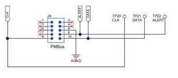
    1. In Application/Evaluation module, No Pull up are used for PMBUS interface, Does it really required to add pull up for PMB_CLK & PMB_DATA pins?
    2. If pull up is required, Can we connect pull up resistors on these signals (PMB_CLK & PMB_DATA) to 5V on Board power supply or do we need to connect with USB adapter 3.3V Pin? (On board 3.3V supply will be up after FPGA program)
    3. USB adapter PMBUS pins are 3.3V logic and TPS549D22 PMBUS pins may go upto 5V, I think this is not an issue because in evaluation board also its connected directly, refer the attached image. 

    Awaiting for your response, please consider this on high priority.

    Regard's

    Raghavendra M

  • Hi Raghavendra, 

    To answer your questions:

    1. If using an EVM and TI USB adapter, pullups are not required since the USB adapter will have internal pullup resitors.

    2.If you use the device on a system in which the PMBus driver does not have internal pullups, the PMBus lines may be pulled up to 5V or 3.3V so long as the thresholds specified in the datasheet are achieved for logic High and logic Low.

    3.Yes, you are correct in that the PMBUS pins are driven with 3.3V logic using the USB adapter. The  datasheet specifies the maximum voltage of the PMBus pins as 6V, so please consider that the limit.

    Sincerely,

    Alec Biesterfeld

  • Also, TI does not offer pre-programming, but you may reach out to our vendors as some of them do offer that service.

    -Alec

  • Hello Alec,

    Thanks for your continuous support. WIth this am closing ticket.

    Regard's

    Raghavendra M