This thread has been locked.

If you have a related question, please click the "Ask a related question" button in the top right corner. The newly created question will be automatically linked to this question.

UCC5390: Controlled power to motor drive circuits

Part Number: UCC5390

Hi don,

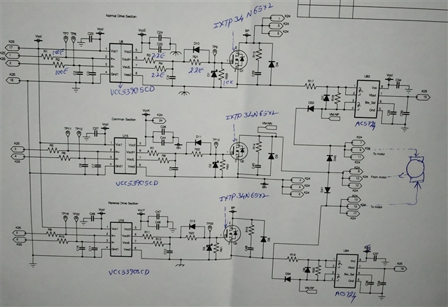
An reply to earlier question, the schematic has been attached here. The DC motor works at 110V and has three terminals forward, reverse and common path for return. Is the circuit shown in the schematic OK? The same circuit we intend to use for vital power control circuit.  I would be of grateful with your inputs.

Regards,

Murthy.

  • Hi, Murthy,

    Nice to hear from you again!

    The schematic looks good. You could simplify it a little if you would like. You don't need D10, 11, and 12; or R21, 22, and 23. These components are to make an asymmetric turn-on and turn-off time, but the OUTL and OUTH do the same thing. You can change R3, 7, and 11 to be 4.4 ohms, and then delete the diodes and resistors mentioned before.  This will give you 4.4 ohms in the turn-on path, and 2.2 ohms in the turn-off path. This will save you a handful of components.

    Let us know if this isn't clear, or if you need further details.

    Best regards,

    Don