Dear Ti,
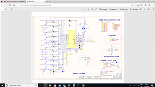
I have custom board with Bq76930 , which when put to Load cell-0 Voltage varies with 30-50mV from Actual , please some one comment here , am wondering whjy it must be happening.?
Thanks ,
Rohit
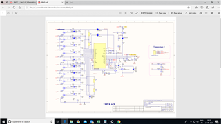
Dear Ti,
I have custom board with Bq76930 , which when put to Load cell-0 Voltage varies with 30-50mV from Actual , please some one comment here , am wondering whjy it must be happening.?
Thanks ,
Rohit