This thread has been locked.

If you have a related question, please click the "Ask a related question" button in the top right corner. The newly created question will be automatically linked to this question.

TPS62160-Q1: TPS62160-Q1 designed for 3.3V,but it generates 3.19V only

Part Number: TPS62160-Q1
Other Parts Discussed in Thread: TPS62162-Q1,

Dear Sir,

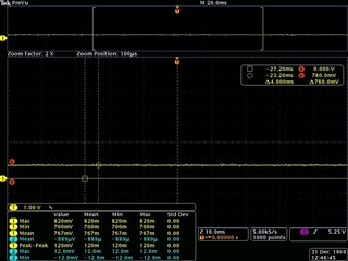
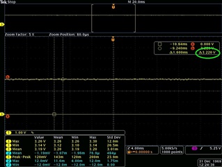
We are using TPS62160QDSGRQ1 buck converter in our design to genertae 3.3V. As per our calculation, feedback resistors are R1=470K & R2=150K. But the output voltage generated is 3.19V only. We have checked the Vfb , which is 0.755V only. I have attached the schematics also. Input voltage provided is 12V.

3v3 buck converter.pdf

Regards

Ebin

  • Hello Ebin,

    Are the resistors R1 and R2 rated for 1% or 5% tolerance?  If 5% resistors were used then a worst case of 3.07V could show up on the output voltage given your selection of R1 and R2.

    For your application of 12V to 3.3V regulation it may be advantageous to use the TPS62162-Q1 version of this part that is already programmed to output 3.3V. It doesn't require the use of R1 and R2 which reduces the number of parts for the design.

    Another reference for this is found in the datasheet in Section 9.2.2.1.

    Thanks,

    Joseph

  • Dear Joseph,

    1% resistors are used in feedback circuit. We cant able to change the part since we already manufactured the boards.

    Regards

    Ebin

  • Hello Ebin,

    I would recommend the following:

    1. Clean the device around the FB pin area with water to remove any residual flux.

    2. Use lower valued resistors for R1 and R2 to achieve a more accurate and robust design.

    The FB pin should be regulated to achieve 0.8V.

    Let me know if this helps.

    Thanks,

    Joseph

  • Dear Joseph,

    I have cleaned the area of FB pin and ensured that there is no flux. Both R1 & R2 are 1% tolerance.

    Regards

    Ebin

  • Hello Ebin,

    The 1% resistors should be good on the tolerance. The value of the feedback resistors could also be lower to increase accuracy (ex. R1=47K, R2=15K). This would draw slightly more current from the output but could help with accuracy issues.  This also may not be helpful if you can't change the manufactured boards.

    Where are you measuring the output voltage from (left or right side of the ferrite bead)?

    And under what load conditions are you testing (full load, no load)?

    It may be helpful to have measured waveforms of Vout (both sides of the ferrite bead), and Vfb if a test setup is available. This would help us debug the situation further.

    Thanks,

    Joseph

  • Dear Joseph,

    I have tried with the resistors 47K & 15K, but the result is same. I have attached the waveforms of Vout after & before ferrite bead and also for the feeback voltage. I have tested with load & no load conditions, both shows same result. All ICs are working fine which is connected to this 3v3 rail.

    Regards

    Ebin

  • Hi ,

    will reply later.

    BRs,

    Young

  • Hello Ebin,

    The output voltage at 3.22V is reasonable because the TPS62160-q1 has feedback voltage accuracy of +/-3% in PWM mode.

    My recommendation would be to recalculate the resistors to give a slightly higher output voltage to compensate for this accuracy and for the voltage drop across the ferrite bead.

    I calculated 1% resistors to be R1=48.7k, R2 = 15k (you can also try R1=487k, R2=150k if it is more convenient for your design), 

      I used Vref=0.78V (per your measured value) and calculated Vout = 3.312V. 

    If you want more margin (slightly higher output voltage) you can even use the next highest 1% resistor for R1 (49.9k).

    Let me know if this helps.

    Thanks,

    Joseph