This thread has been locked.

If you have a related question, please click the "Ask a related question" button in the top right corner. The newly created question will be automatically linked to this question.

TPS51916: PSpice Modeling and Use-Case Simulation - Non-Convergence Problems

Part Number: TPS51916

Hello TI Support Team and Community,

I am working in the standard Cadence PSpice, and not the PSpice for TI variant. 

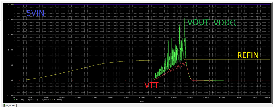
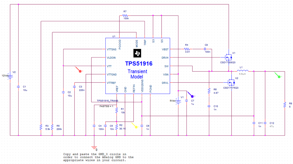
There appears to be an issue with the bias point in my schematic and possibly an issue with the model. The VREF voltage is coming out as 0V, and so no switching is really occurring as the REFIN sees 0V. 

This is using the TPS51916 Transient model... So I am unsure how this model needs to be used... When I run a transient, the bias point appears to cause a problem as the REFIN sees 0V. I had to use the auto-convergence in order to even get the simulation to run because there were convergence problems noted within nodes of the TPS51916 model. There are no other complex devices in the schematic that appear to be causing issues...

Would you have any hints about what could be causing this kind of an issue? Are these models only valid in the PSpice for TI variant, and not valid for standard Cadence PSpice?

Thank you in advance. 

  • Hi Donald,

    I simulated the model downloaded from TI.com using standard Candence PSPICE, and I can see the part switching. Please see the picture below. Can you generate your model based on the one from TI.com to see if it works (or simulate the one from TI.com first)?

    The bias points only gives your the initial condition, in this case 0V on VREF and REFIN is correct, since the part has not been powered up yet. 

    Regards,

    Weidong

  • Hi Weidong,

    Thank you very much for the assistance. I see that a large part of my issue may have been related to not using a long enough simulation time. After extending the simulation time to several hundred us, I see the start of switching. I then see the supply appear to shut off for a reason I have yet to determine. 

    I don't see anything wrong with my schematic... I will try rebuilding it from scratch to see if there is anything I have connected improperly. Do you see any obvious issue with it, by chance? I pretty well just copied this over from Webench, but perhaps I missed something. One last note, the 5Ohm load was added after running simulations without a load, and the results are the same. I also had a 100Ohm load at one point, and that did not have any impact.


    Thank you,

    Donald

  • Hi Donald,

    Can you make below changes to see if the problem goes away?

    1. Change R5 to 1k to support ceramic output capacitance.

    2. Change R3 to 50k to increase OC limit.

    3. Add another 2x47uF at output.

    Regards,

    Weidong

  • Hi Weidong,

    The circuit is starting up just fine now. I used a 1.8Ohm ESR 47uF capacitor as recommended by Webench, but I did not verify it against the datasheet with the rest of my components. Perhaps some of the modifications I made with inductor and FET selection didn't agree with that capacitor choice and I did not re-compute. 

    I will go ahead and experiment some more with this circuit and see if I can get the normal D-CAP function working correctly.

    Thank you,

    Donald