This thread has been locked.

If you have a related question, please click the "Ask a related question" button in the top right corner. The newly created question will be automatically linked to this question.

TPS723: TPS723 power issue

Part Number: TPS723
Other Parts Discussed in Thread: LM2662

Hello Seniors:

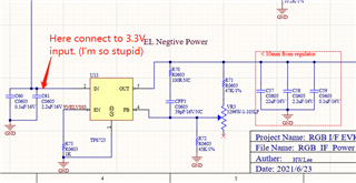
Due to my personal design and negligence, the input voltage is positive.
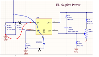
So I can connect the IN of TPS723 to the input GND. Then the input 3.3V is connected to the GND of TPS723? This will work properly?

Because I currently lack a set of negative pressure input. And my circuit boards are all positive pressure.
Is there a faster way to generate a negative pressure to TPS723?
Please also help provide ways to improve.

  • Hi Simon,

    From the LDO's point of view this will work, because the LDO will see a negative voltage from GND to Vin.

    However any other IC's which would be connected to the LDO's output and the GND plane will see the LDO's output voltage as a positive voltage. If you think about how an LDO works the output voltage is always between Vin and GND, since your Vin is now 0V and the GND pin is 3.3V that means the output voltage will be positive relative to the board's 0V ground plane. So the LDO's load would need to be isolated from the board ground and connected to 3.3V, plus you'd have to change all of the caps and resistor dividers for the LDO so that their GND connection is now 3.3V as well. 

    So unfortunately there isn't an easy way to address this, you'll need to bring in or create a negative voltage using an inverting switching regulator.

  • Hi Kyle

    First of all much thanks for your kindly reply.
    I have revised the connection of the TPS723.


    Power in ->  TPS723 GND
    Power in GND -> TPS723 VIN, and I measure the TPS723 output I got the 2.07V(Positive voltage) My power in is 4.35V.

    I expected it to provide a negative pressure output, at least I can verify it first.
    Can you please give me some guidance, could I do something wrong?

    I put the modified figure at below.

    Thanks.

  • Hey Simon,

    There are three things I can think of which may be causing this:

    1. Is this the same TPS723 that you powered with a positive Vin? If so you may have damaged the LDO by exceeding Abs Max voltages listed in the datasheet. 
    2. Did you change the orientation of your DMM so the reference probe (typically ground) is now connected to Vin? 
    3. Did you also edit your board so that any component connected to the LDO Vout is isolated from all other voltages on your board so they are only referencing the LDO GND pin (3.3V)? 
      1. If you had everything connected to a GND plane, this may be hard to accomplish. 
  • Hi Kyle:

    Yes, you are right.  Everything on my circuit connected to a GND plane.

    I searching from the website and found the LM2662 which can convert the Vin to negative Vin.

    I think add this chip and connect toTPS726’s input. Maybe can solve my problem, and I also can adjust the negative output to fit my application.

    How about this idea, would you please give me some suggestions?

    Simon

  • Hi Simon,

    Yes that looks like a good option since it inverts the positive input voltage to a negative one and then the TPS723 will operate from that. 

  • Hi Kyle

    Much thanks for your reply. I'll try this solution and will share the result to you.

    Simon

  • Hi Kyle:

    It's done, it works. Much thanks for your kindly support. Here is the video. Share with you.

    Thanks again

  • Hey Simon, 

    Awesome, thanks for following up.  it's cool to actually be able to see the application working properly!

  • Hi Kyle

    Our company is a Micro OLED display design company, and the video is an SXGA type display.

    I am responsible for firmware, hardware, ME design, so this is why I need to debug the hardware first.

    I will modify my hardware with this solution.
    Much thanks for your kindly support.