This thread has been locked.

If you have a related question, please click the "Ask a related question" button in the top right corner. The newly created question will be automatically linked to this question.

BQ2970: Protection IC does not seem to be cutting off current drain at under-voltage protection

Part Number: BQ2970
Other Parts Discussed in Thread: TIDA-00712, , BQ25120, CSD83325L

I have made a circuit design that very closely mimics the TIDA-00712 reference design. Long story short, my battery is always connected to the circuit and I am seeing the battery drop to levels as low as 1.5V after a week of non-use. This is not what I believe the expected behaviour is. 

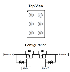
When the battery is outside of the normal operating range (i.e. below 2.8V for BQ29700), I see 40 uA constantly being drained from the battery. According to the specs for BQ29700, the IC has a current pull of ~4 uA in Normal mode and 0.1 uA in lower power mode. I would like help in understanding where the extra current drain is coming from.

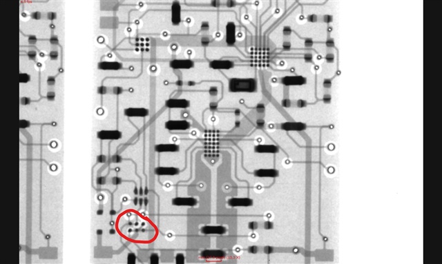
I have attached my schematic for  
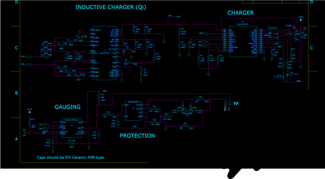
reference, and can attach the PCB layout as well if needed.

  • Hi Joshua,

    Have you been able to measure the state of the FETs? Is the DSG FET open like it should be?

    For finding where the 40uA is flowing I recommend measuring across different resistors in the system looking for voltage drop. I do not see anything incorrect in the BQ2970 portion of the schematic.

    Best regards,

    Matt

  • Hi Matt,

    For the BQ29700 IC, the DOUT pin reads 0V and the COUT pin reads VBAT (Same voltage as positive pin of battery).

  • I am also seeing about 16 uA into the BQ29700. I am seeing a 0.005V drop over R12 going into pin 5 of the protection IC.

  • Thanks Joshua,

    Are you able to trace down where the additional current (of the 40uA) is flowing?

  • I was not outside of the BQ29700. There does not seem to be any good resistors use to isolate current anywhere else in the design. Any suggestions?

  • 16uA for BQ29700 seems to be too high for the IC. Based off the datasheet, I would expect around 0.1 uA for power down mode. Or even if the IC somehow remained in Normal mode, the max current should be 5.5 uA. What am I missing?

  • Yes, it does seem high. When the part goes to the under-voltage state, the V- pin should pull up to the BAT voltage and the current for the part become very low. Can you check the voltage of the V- pin?

  • The V- pin voltage is not pulled to BAT Voltage. The voltage is basically GND. 

  • Hi Joshua,

    How does CELL+ connect to the load and charger?

    Where does BAT go?

    R13 and R14 show DNI, are the patterns open with no contamination?

    Have you confirmed the values of R17 and R18?

    If you have more than one... Do multiple boards do the same thing?

    When the BQ2970 goes to under voltage (data sheet 9.4.3 Over-Discharge Status) it pulls V- up to BAT.  Any load on the system should also pull GND (V-) up to BAT.  If they don't get within 1.3V as described in the data sheet, it won't go to low power mode.

    What are the voltages of the BQ2970 and the FET with respect to the GND?  

  • The issue is consistent across multiple boards, always a 40uA current leak.

    CELL+ and CELL- connect directly to the battery terminals and I have confirmed that there is no contamination at those junctions or at the open R13 and R14 connections. 

    BAT connection goes from pin C2 of BQ27421 (Gauging) to pin B1/B2 of BQ25120 (Charger).

    Unfortunately I will not be able to get to a multimeter again until next week. I will report back on the voltage then.

  • The voltages of BQ2970: (CELL+ = 2.7V)

    (2) COUT = 2.7V, (3) DOUT = 0V, (4) VSS = 0V, (5) BAT = 2.7V, (6) V- = 0V

    The voltages of the FET:

    B1 = 0V, B2 = 2.7V, A1/C1 = 0V, A2/C2 = 0V

  • I have also checked these conditions on a charged battery (BAT = 3.7V). On that board, DOUT = 0V and COUT = 3.7V... this is also not the expected output, but yet I still get full current from my battery. 

  • Hi Joshua,

    It sounds like your FET is shorted or there is some short in the board. If you have access to a solder xray system you might look for signs of extra solder under the package shorting pins.  I would remove U7 to confirm current stops.  Be sure there is not extra solder under the BGA  You could also remove U6 to see if it has an effect, if it were shorted there should still  be resistance from GND to CELL-.  I don't see another CELL- connection on the schematic, but you would be more familiar with it.  

    With a charged battery and V- = VSS = GND DOUT should be high.  Since it is low either U6 would be bad or DOUT would be shorted.  Solder under U7 may be the most likely candidate for a short.

  • Attached above is an X Ray of the part in question. There does not seem to be shorts under the part. However, when I check continuity between DOUT and CELL- with no power connected to the circuit, it reads a short.  

  • Hi Joshua,

    I agree, the solder should be the black and seems well defined.

    The side-end pins of the package for U7 CSD83325L are the sources, the middle pins are the gates.  See https://www.ti.com/document-viewer/CSD83325L/datasheet/abstract#SLPS198128  In the layout x-ray it is hard to tell what is a trace and what might be a package feature, but the source pins do not look connected, the diagonal feature looks like there may be a gate to source connection, I wonder if that may be your DOUT to CELL- continuity.

    From the recommended package outline pin numbering https://www.ti.com/document-viewer/CSD83325L/datasheet/mechanical-packaging-and-orderable-information#SLPS4713539  A1 and C1 would the the source for the transistor with gate at B1 as in your schematic.

    So the symbol pinout on the schematic and pattern on the data sheet seem to match, but it is not clear if they match the board from the x-ray.  You might check the layout documents, also remove a U7 to see if the traces match the recommended footprint.  Also see if the short is gone without the FET.  If the board footprint is wrong the short may not show until the FET is attached.  If the FET is shorted removing it should open the connection.

  • The board footprint is wrong... that is very frustrating because I grabbed it directly from Ultra Librarian link on product's page.