This thread has been locked.

If you have a related question, please click the "Ask a related question" button in the top right corner. The newly created question will be automatically linked to this question.

TPS543C20: TPS543C20 Ripple Noise Issue

Part Number: TPS543C20

Design the circuit according to Webench:Vin=11-13V、Vout=0.82V、Iout=20A

Ripple noise = 200mVp-p, which is very large.

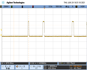
The SW frequency is also unstable.

The actual load is about 1 to 5A, but there is no change in ripple noise.

Also, Vout = 0.85V, which uses the same IC, is more stable.

Are there any possible causes and countermeasures?

Figure 1:Ripple Waveform

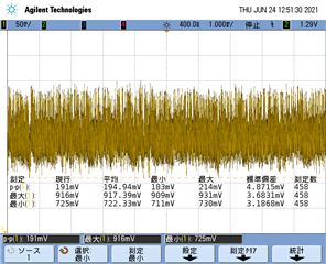
Figure2:Figure1 Zoom
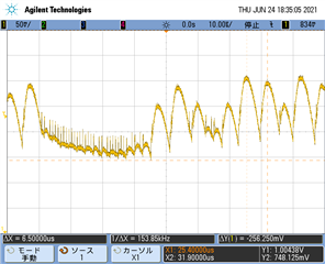
Figure3:SW Waveform

  •  

    It would help if I had the WeBench design / schematic to review, but is appears the output voltage and compensation is unstable, which could be for a variety of reasons.

    The internal compensation is set by the resistor connected from the RAMP pin to GND and is detected at power up.  If the RAMP resistor so not properly connected, or is subject to noise during power-up, it can result in selecting the wrong ramp value, resulting in an unstable loop.

    Externally, the compensation responds to the output voltage as observed by the RSP and RSN pins.  If these pins are not connected to the output correctly, have a poor connection to ground, and include a filter capacitor that has a corner frequency that is too low, it can also result in unstable operation.

    The configuration of the output capacitance, especially parasitic resistance (ESR) and inductance (ESL) from the output capacitor interconnects can also cause the output voltage to become unstable.

    Finally, is the power delivery path from the inductor to the sense point where the RSP pin is connected to the output adds additional inductance between the local output capacitors close to the inductor, and remote output capacitors close to the load and RSP connection point, this can form an additional L-C filter in the output and add additional phase delay between the generated output at the inductor and the sensed output at the RSP connection point, which can destablize the loop. 

    What counter measures can be done to improve the stability depends on the cause of the instability.

    In general, selecting a lower Ramp Capacitor value by changing Rramp will reduce bandwidth but improve stability.

    If the root cause is parasitic resistance or inductance from the interconnects of the output capacitors, then improve the layout or selecting capacitors with lower ESR and ESL will generally improve the stability.

    If the root cause is an additional parasitic inductance between the local output bypass capacitors and remote output bypass capacitors, adding a capacitor from the local output voltage right at the local bypass capacitors near the inductor to feed-forward the local output voltage will generally improve the stability, with some loss of responsiveness at the output voltage.  Typically, the capacitor is signed to provide a 3dB corner frequency lower than the L-C corner frequency of the parasitic inductance and the remote bypass capacitance at the RSP connection point.

  • Thank you for your advice.

     would like to confirm and try it.

  • Hi , 

    sorry that  I will close this threat first. Please re-open it if there is any future question.

    BRs,

    Young