This thread has been locked.

If you have a related question, please click the "Ask a related question" button in the top right corner. The newly created question will be automatically linked to this question.

LM43603: Output voltage too low with load / Works fine with lower indcutance

Part Number: LM43603

Hello All

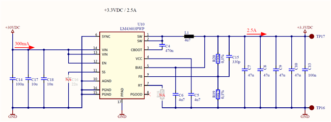
In a no load condition the output voltage in the circuit below is 3.3VDC. With 2.5A load the voltage drops to about 3.0V.

If I increase the inductor value to 6.8uH the voltage drops even more. With a 2.2uH inductor it works fine. According to the datasheet calculation the inductor should be between around 6uH and 12uH.

Why does it work with 2.2uH and not with the theoretically recommended 4.7uH/6.8uH?

Thanks for your help.

  • Hi Robin,

    That is very strange behavior.. Can you share information on the 2.2uH & 4.7uH inductor? What is the saturation current rating for each? If possible, share the datasheet of each inductor. That would be great.

    Thanks,
    Alejandro

  • Hi Alejandro

    I can not find a datasheet of the 2.2uH. It is the ETQP5M2R2YFM (DCR = 9.2m, I = 9.4A, Isat = 17.2A).

    The 4.7uH is the ETQP5M4R7YFM.

    Datasheet:

    AGL0000C59.pdf

    Thanks

    Regards

  • Hi Robin,

    Thanks for sharing the info. The behavior does not make sense. Can you please test the following:

    • Make sure that your input supply is not being current limited
    • Lower Cff value to ~47pF. If the Cff value is too later, it can couple too much ripple to the FB and affect Vout regulation.
    • Can you provide Vin, Vout, SW node, FB waveform for working and non working conditions?

    Thanks,
    Alejandro

  • Hi Alejandro

    Decreasing Cff value did not change anything.

    Here the requested plots (blue = SW, pink = FB, yellow = Vout). Vin was always stable at 30VDC.

    With 4.7uH, no load:

    With 4.7uH , 2A load:

    With 2.2uH , no load:

    With 2.2uH , 2A load:

    Best regards

    Robin

  • Hi Robin,

    The following waveforms are not making sense. SW node voltage is at ~1.6V? SW voltage should be rising up to VIN of 30V.
    I would recommend to stay with the recommended value that the datasheet and WEBENCH recommend. Is there a possibility that the 2.2uH is accidentally being mistaken with 4.7uH?

    Regards,
    Alejandro

  • Hi Alejandro

    Of course you are right, there may was a wrong setting on the oscilloscope. The SW voltage goes up to 30V. But apart from that the waveforms are correct.

    No the inductors can not be mistaken because the value is printed on the component. 

    According to datasheet calcluations, the inductor value would need to be higher (6-12uH) and then the voltage drop is even higher too.

    Any other ideas?

    Regards

  • Robin,

    Please double-check probing on device. SW node should be 30V. It's not making any sense.

    How are you testing the load? Is it a resistor on the output? E-load set as Constant Current or constant restive? What is the output connected to?

    Thanks,
    Alejandro

  • Hi Alejandro 

    As I already said the SW node was measured with a wrong setting. It is 30V, I measured it again. But the shape of the signal is correct.

    The load is a simple resistor.

    Regards

  • Hi Robin,

    Thanks for the verification. Further Ideas: Is this failure occurring on multiple boards or one board? Theoretically it does not make sense. Let's try the following:

    • Can you please try the following ABBA Testing (you will need to swap out IC with new IC). The device might have been damaged when soldered on under temperature conditions. Capture results. Does new IC work with proper calculated inductor value?
    • Can you please provide a top view image of circuit on board? We would like to verify/see if there is any shorts, discoloration, etc.noticeable.

    Thanks,
    Alejandro

  • Hi Alejandro

    I have found the problem. The GND pad was not soldered correctly. After replacing the device I have seen that the GND pad had no solder on it.

    Thanks for your help.

    Best regards