This thread has been locked.

If you have a related question, please click the "Ask a related question" button in the top right corner. The newly created question will be automatically linked to this question.

UCC27210: Device gets damaged

Part Number: UCC27210

Hello, 

is it possible to control a driver with another driver?

As i am working on designing a bldc machine driver but the evaluation board i bought comes with an IC that has embedded integrated smart gate driver.
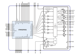
  the controller IC

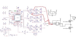
so connecting the pins to the input of the Ucc27210 gate driver

   the gate driver keeps getting damaged and i cant firgure out why.

is it possible to drive the external gate driver with the embedded one ? 

  • Hello Kehinde,

    Thanks for reaching out!

    -------

    You should be able to drive the external gate driver with the embedded one.  My guess is there may be some other things going on.

    I have a few questions:

    1)  Please confirm the Schottky diodes across the power FETs

    2)  Can you tell if the input or output stage is getting damaged on the part?  (This can be confirmed by measuring the impedances of pins on a damaged unit versus a new unit; be sure to measure this while each of the IC's is off the board.)

    3)  How are the input signals from the board?  Are they within the recommended specs of the datasheet?  (Feel free to provide waveforms of the input pins and of the output pins and SW node.

    ------

    I look forward to hearing back from you!

    Thanks,

    Aaron Grgurich

  • Hello Aaron,

    I can confirm that there is supply across the diode,

    the damage is at the input as the input impedance is less by a large factor to a new device 

    The input signals  
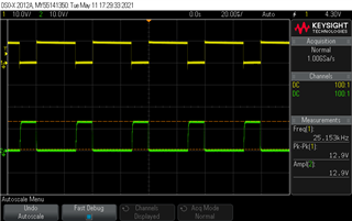
before connecting to the external gate driver 

    the signal at the Ucc27210 gate driver   
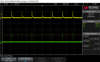
and the device starts making a loud ringing sound. 

  • Kehinde,

    Thanks for taking the time to send the waveforms and measure the pin resistances!

    ------

    I agree, it does seem that the inputs are damaged...

    ------

    Questions:

    1)  With the UCC27210 being wired in separately, is it on a separate board?  If so, is the separate board on the same GND reference and is the GND loop small?

    2)  What happens when / if you replace the "damaged" unit with a new unit?

    3)  Do you know why the Green input signal is a few volts higher than the Yellow input signal?

    -------

    I believe this is the answer: 

    My biggest concern is it seems that one of the integrated gate drive outputs of the smart gate driver seems to still have the bootstrap configuration... and the bootstrap capacitor is referenced to the Switch Node of the output.  This is the connection to the HI pin of the UCC27210.

    The Switch node is able to get up to 24V and if the bootstrap capacitor is referenced to 24V and is already charged to 12V, then the bootstrap effectively is at 36V when referenced to GND, which the UCC27210 is referenced to GND.  Therefore, the bootstrap circuit is putting way too much voltage on the input pin of the UCC27210, way above the Absolute Maximum voltage and damaged the part.  The circuit likely worked for a few cycles and eventually damaged the UCC27210 input.

    -------

    Here are potential solutions (REPLACE THE DAMAGED IC AS WELL):

    1)  Connect the HI pin of the UCC27210 to one of the "LVG#" outputs instead of a "HVG" output from the controller.

    2)  OR, you can cut the connection of the Switch Node that links back to the bootstrap capacitor / the "OUT#" pin of the controller.  Then, connect the "OUT#" pin to GND and that should fix your problem.  You can either keep the bootstrap capacitor or get rid of it.  If you keep it for bypassing purposes, you must have it referenced to GND.

    -------

     I hope this answers your question and fixes you problem.  If so, please press the green button; otherwise, feel free to follow up!

    Thanks!

    Aaron

  • Hello Aaron, with regards to the questions asked 

    With the UCC27210 being wired in separately, is it on a separate board?  If so, is the separate board on the same GND reference and is the GND loop small?

    yes the boards are no the same GND ref. the loop was large as i used a long jumper cable will rectify that.

    What happens when / if you replace the "damaged" unit with a new unit?

    its still getting damaged. 

    Do you know why the Green input signal is a few volts higher than the Yellow input signal?

    that due to the voltage drop due to bootstrapping.

    looking into the high input voltage theory i used a voltage divider   to limit the inputs to the external it still got damaged.

    Connect the HI pin of the UCC27210 to one of the "LVG#" outputs instead of a "HVG" output from the controller.

    and i cant do this because the signals from the HVG and LVG are different.

    OR, you can cut the connection of the Switch Node that links back to the bootstrap capacitor / the "OUT#" pin of the controller.  Then, connect the "OUT#" pin to GND and that should fix your problem.  You can either keep the bootstrap capacitor or get rid of it.  If you keep it for bypassing purposes, you must have it referenced to GND.

    will try this once the new drivers arrive, Hopefully it works...

  • Kehinde,

    Thanks for the informative reply!

    ---

    Interesting with the voltage divider, but my guess is the inputs still get damaged within the first few cycles of the initial powerup.  And I expected that you would have to stick with that output from the controller, so that is fine.

    ---

    Please let me know if it works!

    Thanks,

    Aaron Grgurich

  • yea it works now 

    OR, you can cut the connection of the Switch Node that links back to the bootstrap capacitor / the "OUT#" pin of the controller.  Then, connect the "OUT#" pin to GND and that should fix your problem.  You can either keep the bootstrap capacitor or get rid of it.  If you keep it for bypassing purposes, you must have it referenced to GND.

    will try this once the new drivers arrive, Hopefully it works...

    Thanks for the support